This page provides the links to the NASA Airborne Science Program Website for the SWESARR flight reports.
Author: batu
References
Discussion
This page is to discuss SWESARR data products. If you have a question, please comment below.
Radiometer Data Format
Airborne microwave brightness temperature observations were made at three frequencies (10.65, 18.7, and 36.5 GHz; a.k.a., X, Ku and Ka bands, respectively), at horizontal polarization with a nominal 45-degree look angle. There were repeated acquisitions over the three science target lines, named North, South, and Cross.
Data file is in CSV (comma separated values) format. Each file contains:
- Date & Time (UTC),
- Footprint center Longitude (deg),
- Footprint center Latitude (deg),
- Footprint center elevation (m),
- TB X (K),
- TB Ku (K),
- TB Ka (K),
- Aircraft Longitude (deg),
- Aircraft Latitude (deg),
- Aircraft Altitude (m),
- Aircraft Yaw (deg),
- Aircraft Pitch (deg),
- Aircraft Roll (deg),
- Positioner Roll (deg)
File Naming Convention
For this product, there is one file per pass over a given science line, named for example:
GRMCT1_31603_20009_TB_200212_XKuKa225H_v03.csv
GRM: Grand Mesa, CO
C: Science target line name (either N, S, or C, signifying North, South, or Cross)
Each filename consists of the following components, separated by underscores “_”:
– Site Name: Six character abbreviation for the desired target site (files may contain other sites, e.g., when science lines cross each other).
– Heading and Repeat Count: Three digits aircraft heading (clockwise from 0 degrees due North) followed by an auto-increment alphanumeric repeat counter, showing the repeat passes collected on the same flight (i.e., the counter is reset after each flight).
– Flight Number: Five digits in which the first two digits are the last two digits of the year of the SWESARR flight, and the next three digits are the flight number by SWESARR counted sequentially from the first flight of the calendar year.
– Date (YYMMDD): Six digits, two for year, month, and day (UTC).
– Frequencies, Look angle, Polarization: List of radiometric frequency bands collected by SWESARR (characters), followed by the look angle (three digits), followed by the polarization (one character). Pointing angle is defined as 90 degrees for starboard side, 180 degrees for nadir and 270 for port side. Acquisitions were done with a 45 degree incidence angle port of nadir, resulting in 225 degrees.
– Version: Two digits indicating the processing version number.
– Extension: Three character file extension indicating the data type.
Spatial Resolution
The field of view depends on the frequency of observations and the aircraft altitude. At a nominal elevation of 1,500 ft the spatial resolutions are (across x along track):
- X band 496 m x 352 m
- Ku band 282 m x 200 m
- Ka band 144 m x 102 m
SWESARR is a non–scanning instrument, collecting observations in push–broom alignment at an incidence angle of 45 degrees.
FAQ
SAR data format
SWESARR radar data follows a similar format to UAVSAR and EcoSAR, though they are not exactly the same.
The format of the following files are described:
SLC files (.slc): single look complex files for each polarization (VV and VH), 4-byte floating point format, little endian, pixel interleaved (real, imaginary, 8 bytes per pixel), corresponding to the scattering matrix.
GeoTiff (.tif): geocoded multi-looked radar intensity imagery for each polarization (VV,VH), sampled in a uniform grid, in logarithmic (dB) scale, provided in a single grayscale band. Projection is listed in the annotation file (.ann). Currently default projection is UTM at 2m scale.
DEM files (.tif): The native resolution DEM used for data processing over the same coverage area, in the same projection as the geocoded radar files.
Annotation file (.ann): a text file with metadata.
MLC files (.mlc): (NOT CURRENTLY RELEASED) multi-looked cross products, floating point format, three complex files 8 bytes per pixel, three real files 4 bytes per pixel, little endian.
Ground projected files (.grd): (NOT CURRENTLY RELEASED) complex cross products projected to the ground in simple geographic coordinates (latitude, longitude). There is a fixed number of looks for each pixel. Floating point, little endian, 4 bytes per pixel.
Hgt file (.hgt): (NOT CURRENTLY RELEASED) the DEM that the imagery was projected to, in the same geographic coordinates as the ground projected files. Floating point (4 bytes per pixel), little endian, ground elevation in meters.
File Naming Convention
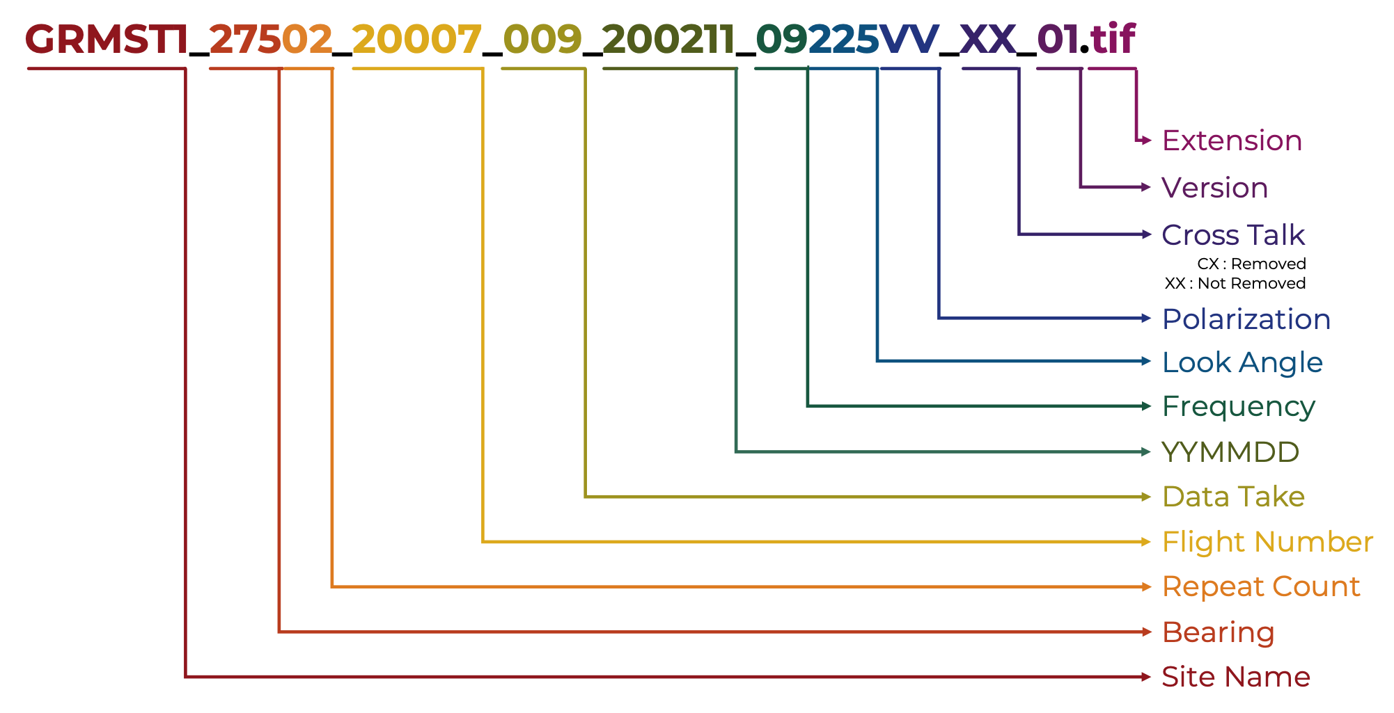
Each filename consists of the following components, separated by underscores “_”:
Site Name: Six character abbreviation for the desired target site (image may contain other sites). A longer site description is provided in the annotation file.
Bearing and Repeat Count: Three digits aircraft heading (clockwise from 0 degrees due North) followed by an auto-increment alphanumeric repeat counter, showing the repeat passes collected on the same flight.
Flight Number: Five digits in which the first two digits are the last two digits of the year of the SWESARR flight, and the next three digits are the flight number by SWESARR counted sequentially from the first flight of the year.
Data Take Count: Three digits indicating the data take count, counted sequentially from the beginning of the flight. Flight number and data take count defines a unique dataset.
Date: Six digits in which the first two digits are the last two digits of the year of the flight, the next two digits are the month the acquisition was acquired, and the last two digits are the day of the month of the acquisition (UTC) (eg. YYMMDD).
Frequency, Look angle, Polarization: Between 3 to 9 characters, two digits indicating the frequency band in GHz, followed by the look angle (three digits) followed by the polarization. The polarization may be between 2 characters (first character is the transmit polarization, and second character is the receive polarization) and 4 characters (if the file represents a cross product). Pointing angle is defined as 90 degrees for starboard side, 180 degrees for nadir and 270 for port side. Currently imaging is done at 45 degrees port of nadir, resulting in 225 degrees. Frequency and Polarization are omitted in product wide names (e.g. for annotation filename)
Cross Talk: Two characters indicating whether cross talk has been calibrated or not. XX – no cross talk calibration. CX – cross talk calibration has been applied.
Version: Two digits indicating the processing version number.
Extension: Three character file extension indicating the data type.
Examples:
Product Name: GRMST1_27502_20007_009_200211_225_XX_01
Annotation File: GRMST1_27502_20007_009_200211_225_XX_01.ann
Geotiff File: GRMST1_27502_20007_009_200211_09225VV_XX_01.tif
where GRMST1 is the site name, 275 degrees is the heading of SWESARR in flight, with a repeat counter of 02, the flight was the 007th flight in 2020, this data take was the 009th data take during the flight, the data was acquired on February 11th, 2020 (UTC), the frequency band was 09 GHz (X-band), pointing at 225 degrees (45 deg. on the port side of plane), this file contains the VV data, with no cross talk calibration applied, this is the first iteration of processing,and the data type is tif.
Data format description
SLC data:
The SLC is a pure binary file (complex floating-point, 8 bytes per pixel) with no header bytes. The number of lines and samples are entered in the annotation file as .rows and .cols fields respectively (e.g. slc09vv.rows). There is a separate file for each polarization channel (VV and VH). The pixel spacing in meters is given in the annotation file by .row_mult and .col_mult for the azimuth and range directions, respectively. The projection of the data is in the natural slant range projection. The geographic coordinates of the data are defined by the ” Peg position and heading”, and by the cross track and along track offset of the upper left pixel (given by set_plat, set_plon, and set_phdg, and .row_addr and .col_addr in the annotation file). The byte order is little endian. The units of the data are defined in the field SLC Data Units, and is by default in linear radar amplitude (rather than dB units).
Annotation file:
The annotation file (.ann) is a keyword/value ASCII file in which the value on the right of the equals sign corresponds to the keyword on the left of the equals sign. The number of keywords may change with time, so the line number should not be assumed to be constant for any given keyword. In addition, the spacing between keywords and values may change. The units are given in parenthesis between the keyword and equal sign, and may change from annotation file to annotation file and within each annotation file. Comments are indicated by semicolons (;), and may occur at the beginning of a line, or at the middle of a line (everything after the semicolon on that line is a comment). The length of each text line is variable, and ends with a carriage return. There may be lines with just a carriage return or spaces and a carriage return.
When using mdx to display the data files, use the corresponding display parameters in the annotation file. Use mlc_pwr to display the three real (4 byte per pixel) MLC data: HHHH, HVHV, and VVVV. Use mlc_mag and mlc_phase to display the three complex (8 byte per pixel) MLC data: HHHV, HHVV, and HVVV. Similarly, use grd_pwr to display real (4 byte per pixel) GRD data. Use grd_mag and grd_phase to display complex (8 byte per pixel) GRD data.
Geotiff:
GEOTIFF data is generated using the multilooked SLC imagery. SWESARR projects slant range images to ground range using GDAL Geolocation arrays (GDAL-Geoloc). Ground positions for multilooked SLC is calculated at each pixel, which is then used in the GDAL inversion. The annotation files include the size (.rows, .cols), Projection (.proj), coordinate of upper left pixel (row_addr, col_addr), spacing (.row_mult, .col_mult), recommended data value stretching (.val_mult, val_min, val_max) and other parameters. These files are intended to be fully compatible with GIS software.
MLC data (NOT CURRENTLY RELEASED):
The MLC is a pure binary file with no header bytes. Three of the files are complex floating point, 8 byte per pixel. These complex products are derived from the average (usually 1 pixels in range, and 10 pixels in azimuth, given precisely by “Number of Range Looks in MLC” and “Number of Azimuth Looks in MLC” in the annotation file) of the product of each SLC pixel and correspond to: SvvSvh*
Three of the files are real floating point, 4 bytes per pixel. These real powers are derived from the average (usually 1 pixels in range, and 10 pixels in azimuth, given precisely by “Number of Range Looks in MLC” and “Number of Azimuth Looks in MLC” in the annotation file) of the product of each SLC pixel and correspond to: SvvSvv*, SvhSvh*
The number of lines and samples are entered in the annotation file as .set_rows and .set_cols respectively. There is a separate file for each product. The pixel spacing in meters is given in the annotation file by .row_mult and .col_mult for the azimuth and range directions, respectively. The projection of the data is in the natural slant range projection. The geographic coordinates of the data are defined by the “Peg position and heading”, and by the cross track and along track offset of the upper left pixel (given by set_plat, set_plon, and set_phdg, and .row_addr and .col_addr in the annotation file). The byte order is little endian. The units of the data are define in “MLC Data Units” field.
GRD data (NOT CURRENTLY RELEASED) :
The grd files consists of three real floating point, 4 bytes per pixel, and three complex floating point, 8 bytes per pixel files. The number of lines and samples may be found in the annotation file and are given by .set_rows and .set_cols respectively. The grd files contain projected multi-looked data for cross-products.
HGT data(NOT CURRENTLY RELEASED):
The height file is a pure binary real*4 floating point file where the number of lines and samples may be found in the annotation file and are given by hgt.rows and hgt.cols respectively. This height file contains the values of elevation used to project the slant range data to the Earth’s surface. The value of the ground elevation is given in meters. The datum is given by “DEM Datum” in the annotation file. The source of the DEM is given by “DEM source” in the annotation file. The data is in an equiangular coordinate system in which each line and pixel increments in latitude and longitude by hgt.row_mult and hgt.col_mult degrees from the upper left corner coordinate given by hgt.row_addr and hgt.col_addr
This file is co-registered to the GRD files.
References:
Data
Radar Data Format and Versions
| Version | Release Date | Campaigns | Description | Details & Access |
| V1 | 8/27/20 | Grand Mesa | Processed using Extended Chirp Scaling with MoComp | Link to SAR_V1 |
| V2 | 7/26/23 | Grand Mesa | Sample imagery processed with Time Domain Back Projection to a DEM | Link to SAR_V2 |
| V3 | 9/21/23 | Grand Mesa and AK | Sample imagery processed with Time Domain Back Projection in radar geometry | Link to SAR_V3 |
| V3.1 | 6/6/24 | Grand Mesa and AK | Similar algorithm to V3 but with preliminary calibration of X-VV band only | Link to SAR_V3.1 |
| V3.2 | TBD | Grand Mesa and AK | Similar algorithm to V3 but with all bands. | Link to SAR_V3.2 |
Pre-release radar data is available here: https://glihtdata.gsfc.nasa.gov/files/radar/SWESARR/prerelease/
Albums
[wppa type=”cover” album=”1″]