J-2X Progress: Engine Assembly, Volume 3
Assembly of J-2X development Engine 10001 “officially” commenced on Monday 21 February of this year, just about a month ago. In even more important news, my own household had an eight-pound, eleven-ounce new arrival on Friday 11 February. No, no, not that kind of arrival. Rather, it’s a new puppy named Kate (…had ya fooled for a moment, didn’t I?).

Thus, I have the great pleasure of spending this spring watching both J-2X Engine 10001 and Kate grow up and into what they will finally become. Here is a picture of Kate cuddled with our cat Cassady to give you an idea of her size when first she came home. By the way, the cats all thought that Kate was just swell so long as she was unconscious and inert. Their opinion changed significantly when she woke up.
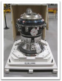
And here was the “engine” as a pup, newly weaned and delivered to Stennis Space Center. It began as just the Main Injector stacked on the Main Combustion Chamber. Humble beginnings.
Here is the engine today. Awwwww, our little baby is growing up so fast!
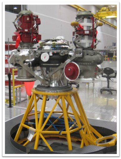
The most noticeable additions since the last time that we checked in on the assembly progress are the two inlet ducts stacked on top of the two turbopumps. More stuff has been going on, like the attachment of brackets and mounts for parts to follow, but those two ducts are the biggest items. So, let’s talk about them…
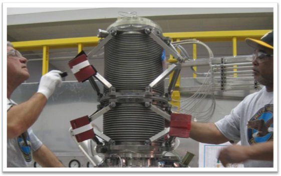
In the picture of the stacked engine assembly, the inlet ducts are encased in protective coverings. In the picture above, however, these coverings have been largely removed from the fuel-side duct for inspection purposes. It looks kinda funky, huh? Well, despite the oft-demonstrated good fashion sense and excellent taste of your average rocket scientist, we don’t usually make thinks look funky just so they look cool. There is usually a function to our funky-ness.
Here is the function: The engine has to gimbal. What that means is that you have to be able to point the engine in slightly other directions besides straight down from the back of the vehicle stage. You can think of gimballing as being like a rudder on the back of a boat but in three-dimensions. Thus, the whole engine has to pivot around when pushed or pulled by two large hydraulic actuator arms from the stage.
In order to accommodate this movement of the engine, the inlet ducts need to be able to bend and flex and even twist a little bit. So, in order to make super-duper-strong metal ducts flexible, you have to add the convolutions like you see above. It’s very much like one of those twisty drinking straws that I absolutely loved as a kid (see, even then I was unconsciously thinking about rocket engine components). If you bend a regular drinking straw, the thing collapses in on itself. If you bend one of those twisty drinking straws with the convolutions, the straw remains useful as a duct. The external structures in the picture of the inlet ducts, those shiny triangular brackets hinged together, hold the whole thing together under operational conditions.
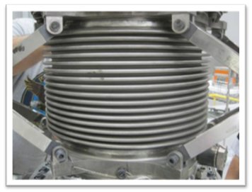
Here’s a neato little fact about the fuel-side inlet duct. In order for the convolutions to do their job by allowing movement, you can’t have any ice buildup in the convolutions. Liquid hydrogen is so cold that it can freeze nitrogen right out of the air. If you don’t have some way to insulate this duct, it would be covered in nitrogen ice while sitting in compartment at the back of the stage. But you can’t insulate it on the outside or, again, the thing can’t flex. So, what we’ve done is make the whole thing into a Thermos® bottle. There are actually two walls of convolutions, an inner wall and an outer wall. In between is a vacuum and that vacuum provides the insulation. This feature is not necessary on the oxidizer side since liquid oxygen will not freeze anything out of the air other than moisture. Thus, so long as you keep the compartment free of humidity, the oxidizer side is fine with only one layer and bare metal (though special accommodations are necessary on the test stand where the ambient environment cannot be so carefully controlled).
So, that’s the status of the J-2X Engine 10001 assembly and a description of its inlet ducts. The status of Kate is that she is growing like a weed. Every day her legs look longer. Of course, it was only after we adopted her that the shelter people seriously and openly speculated that the father might, in fact, have been a Rottweiler. Oh dear. She’s nearly 24 pounds at less than fourteen weeks old. The cats are more displeased with each passing day.

Wow! Took me a while to realize those are the FUEL intake ducts! Really does put some perspective on the fuel consumption of the engine. Looks like the ducts are close to a foot in diameter.
Hi: Do the brackets (those triangle angling things) (that hold the hydrogen inlets) stretch to maximum extention during take-off and under power?
How much force does the hydraulics have to push to gimbal the rocket engine when it does?
How hot does it get and how many RPM’s does the turbine get to in what time period?
Thank you.
David
@Anders: Yes, the propellant inlet ducts are big ducts. The flow area is around 8 inches in diameter and, between the two of them, they deliver to the engine well over 600 pounds of liquid hydrogen and liquid oxygen every second.
@David: The inlet ducts don’t stretch much. Remember, the primary structural connection to the stage is through the gimbal bearing. That’s the point through which the engine pushes and it is extremely rigid to withstand the loads. The inlet ducts themselves only need to compress and stretch by a few inches in order to accommodate the gimbal movements.
Actuator load? Well, it is an interesting fact that traditionally here at NASA it is the stage folks who are responsible for providing thrust vector control. Us engine folks always say, “We push; we don’t steer.” But since we provide the connection points for the stage actuators, we do need to know what kind of oomph they deliver. For export control reasons, I cannot provide specification type exact numbers, but it is on the order of tens of thousands of pounds-force.
How hot? Well, depends what you’re talking about. The hottest part of the engine is the combustion process in the main chamber. Peak temperatures there are on the order of 6,000 degree Fahrenheit.
Turbine RPMs and ramp up? Typical of most spin-start, GG-cycle engines, the J-2X is up to full power somewhere between 3 and 4 seconds after receiving a start command. The two turbopumps rotate at different speeds. This is because of the huge differences in the density of the two propellants. Liquid hydrogen is around 4 lbm per cubic foot. Liquid oxygen is over 70 lbm per cubic foot. While it is possible to pump both of these fluids on a common shaft (the Russians have done it), it’s not easy and it’s not necessarily the best solution. Again, like most high-pressure LH2/LO2 engines, the turbopump speeds for J-2X are typical. On the LH2 side it’s around 30,000 rpm and on the LO2 side it’s around 12,000 rpm. Again, for export control reasons I cannot provide true power balance estimates or spec values, but these are in the neighborhood.
Hope that helps.