I’ve had jobs of some flavor almost continuously since I was fourteen years old. From delivering newspapers to cutting grass to flipping burgers to showing movies to mixing giant vats of coleslaw to instructing an aerodynamics laboratory course to hand counting vehicular traffic to researching the derivation of combustion stability equations, before I finally settled into something resembling a career (and while I was winding my way through the maze of secondary and higher education), I did all kinds stuff. But when I did get my first job after graduate school it was doing test data reduction and performance calculations for the Space Shuttle Main Engine (SSME).
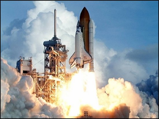
In past articles we’ve discussed rocket engine performance. We’ve talked about the “Big Three” operational points and performance measures that characterize an engine: thrust, mixture ratio, and specific impulse. Okay, but how do we know what these values are for any given engine? I mean, we can do calculations with analytical equations, formulas, algorithms, or models that tell us what these parameters ought to be for a given rocket engine design; but when I’ve got an actual rocket engine sitting in front of me — a big, shiny, complex hunk of metal standing ten feet high and weighing thousands of pounds — how do I know how it actually functions and performs?
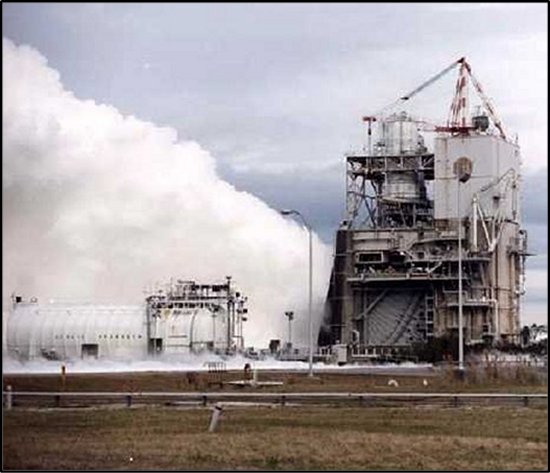
Well, duh, you test it. Of course! But making smoke and fire (and steam) does not, by itself, give you any data. The most that you could say from just watching an engine test is that it’s really, really noisy and that it makes a really, really big exhaust plume. So, more than just observe, you have to take measurements during the test. That’s how you get data. As I’ve said many times, there are only two reasons to conduct rocket engine tests: (1) to impress your friends, and (2) to collect data. In order to get data on the “Big Three,” you need to measure thrust and you need to measure propellant flowrates. For this article, we’re going to focus on propellant flowrates. I will talk about thrust measurement in the next article.
Propellant flows are measured on a rocket engine test stand with “propellant flowmeters.” Makes sense, right? But calling something a “meter for flow” doesn’t tell you how it works. That’s like saying, “How do I make popcorn?” Answer: “With a popcorn maker.” No kidding. Thank you for playing and you’ve conveyed no useful or interesting information.
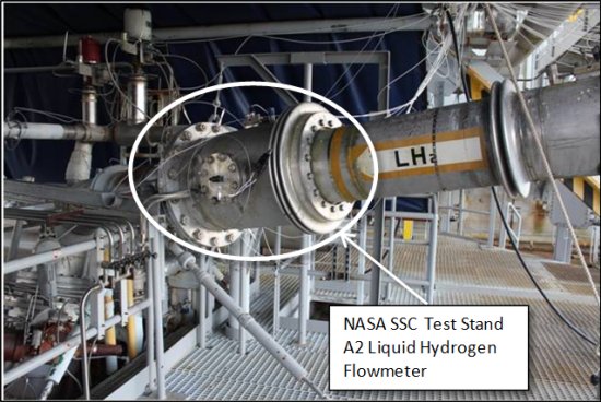
There are a number of different ways to measure fluid volumetric flow. The units that we use for the very large flowrates feeding an engine are turbine flowmeters. Have you ever blown into a small fan that’s turned off or perhaps a pinwheel? If you blow hard enough, you can make the fan or pinwheel spin. That is, quite simply, how a turbine flowmeter works: it’s a fan, i.e., turbine, stuck in a tube that spins as fluid flows through it. The faster the fluid flows, the faster the turbine spins. The thing that we measure is the speed of the turbine spinning. The turbine has a number of blades (just like that small fan that you blow into). We pick a spot on the tube in which the turbine sits and count how many blades pass by. If we count, say, ten blade passes in a second, then there is more flow than if we’d only counted eight blade passes in a second.

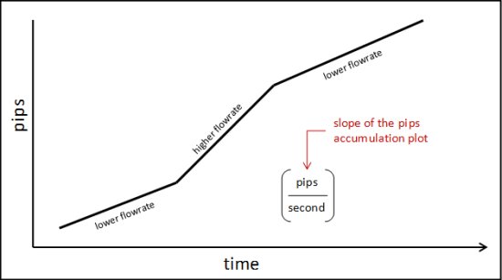
So, how do we count blade passes? Well, there’s a little window in the side of the propellant duct and we sit a young college co-op in front of the window with a little hand clicker and scream “GO!” from the blockhouse… Okay, I’m fibbing. We don’t treat our co-ops nearly that bad. Usually. Besides, there would be no way that the human eye and brain could keep up since we’re talking about hundreds of blade passes per second. Instead, we measure it electronically. Each blade contains a magnet in the tip. The sensor on the outside of the tube is activated by the magnet. Each magnet pass generates an electronic pulse or blip — what we call a “pip” — and we keep a continuous count of these accumulated pips. The pip count is then recorded with each time step in the data collection process. Then, after the test, we can translate this ever-increasing pip count into a pip-rate based upon these recorded times. Mathematically speaking, the pip-rate at any given point is the slope of the pip-count plotted against time.
In order to translate a pip-rate into a volumetric flowrate, such as gallons per minute (gpm), the flowmeter needs to be calibrated. We need to know how much flow is required to generate a blade passage, i.e., a pip. If, for example, we knew that the passage of one gallon was enough to move the turbine exactly one blade pass of rotation, then a measured 100 pips-per-second would equal 100 gallons-per-second, or 6,000 gpm. Thus, calibration of a flowmeter consists of flowing a known volume of fluid through the meter and counting the pips read:

The truth is that it’s a bit more complicated in that the calibration varies with the speed of the turbine due to kinetic and mechanical issues of the rotating hardware and due to fluid dynamic effects of the fluid interacting with the turbine blades. However, these are secondary effects as compared to the simple notion of figuring how much a pip is worth in terms of volume.
Luckily enough (or, really, strategically enough), the engine test stands are themselves set up to function as a calibration facility for the flowmeters. This is because the propellant tanks have a known geometry and are equipped with fluid level sensors.
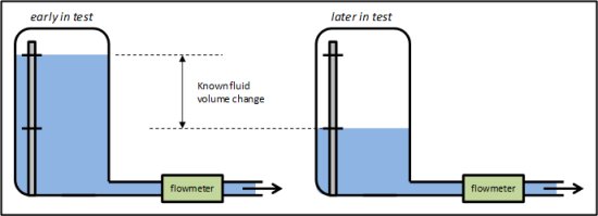
As shown in the figure above, if we know at a particular time the height of the fluid in the tank and then, at a later time, we know a lower height of the fluid, then, using tank geometry, we know the volume of fluid that exited the tank and ran through the flowmeter. In practice, we actually perform this calibration during an engine test. That way we can be assured that the flowmeter rotor is spinning at a speed representative of where we’ll need measurements.
An observant reader would note here that if we know the volume consumed over time just from the level sensors in the tank, then we don’t need a flowmeter in the middle. All you need is volume divided by time, right? The problem is one of fidelity. Because the level sensors are discrete points on the pole submerged in the tank, the measures of volume used for calibration are relatively big chunks, as in enough propellant to run the engine tens of seconds. In order to get a decent calibration across several discrete level sensors, we typically need to run between 100 and 150 seconds of steady, mainstage engine conditions. The use of a calibrated flowmeter allows you to see variations in flowrate at much smaller time increments and this allows us to collect and observe more data with regarding to engine characterization at different conditions. You can almost think of the flowmeter as a useful interpolation tool between large chunks of time and consumed propellant.
You will note that so far we’ve just talked about volumetric flowrates and yet, when we talk about engine performance we refer to mass flowrates. The difference between the volume and the mass of something is its density. For our very pure propellants, fluid density is simply a function of fluid temperature and static pressure. So, we take temperature and pressure measurements immediately downstream of the flowmeter and, using either an interpolated look-up table or empirical curves, we can get density. So, you put it all together and you end up with something along the lines of the following:
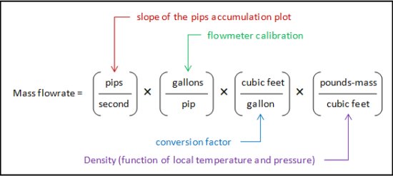
That is how you measure and calculate the mass flowrate of the propellants flowing through the feedlines and going into the engine using a turbine flowmeter. The item from the “Big Three” to which this can be applied directly is the engine inlet mixture ratio, which is defined as the oxidizer mass flowrate divided by the fuel mass flowrate.
However, depending on the engine and vehicle design, not all of the propellants that go into an engine go overboard. Often, warmed propellants are returned from the engine to the stage to act as pressurizing gases for the stage propellant tanks. On the Space Shuttle, both gaseous oxygen and gaseous hydrogen were flowed back to the stage for this purpose. The rocket equation that essentially defines the parameter we know as specific impulse is only concerned with propellants that leave the vehicle so for specific impulse calculations you need to use inlet mass flow minus pressurization flow.

As compared to the engine inlet mass flowrates, which for large rocket engines can amount to hundreds of pounds-mass per second, the pressurization flowrates are typically less than one or two pound per second. Flows this small are more effectively measured using flowmeters different from the turbine flowmeters I’ve described above. For our engine testing we use Venturi meters for these small flows. Venturi meters use a variable flow area coupled with pressure measurements to feed Bernoulli Equation relationships between pressure and fluid velocity. Once you know the fluid velocity, fluid density, and fluid flow area at any point, you can then calculate mass flowrate (for now, at least, I’ll not go any further with Venturi meter calculations).
This, then, wraps up the story with regards to propellant mass flow measurements and calculations on the engine test stands. In the next article, we’ll go into the measurement of and calculation of thrust. All of this discussion reminds me so much of my first days/weeks/months on the job working with SSME test data. At first, it was just a bunch of bewildering numbers and data reduction tools and rules and calibration factors and work procedures. I had no idea what was going on. But gradually, as I dug into the data and talked to people and dissected the computer codes and tools we used, I began to piece it all together as to what these measurements and calculations actually meant. Seemingly every day brought a new epiphany in understanding. Boy oh boy, that was fun!
