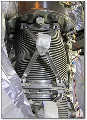
It’s been over six years since I started working on the J-2X development effort. I missed the very first day that the notion of a J-2X engine was conceived, but I was only two weeks late to the party. So, I’ve been with the thing almost from the beginning. And throughout that entire period, whenever I get the chance to talk to people outside of our small, internal rocket engine community (…for very understandable reasons, they don’t let us out much), the single, most frequent, recurring, and ubiquitous question that I hear is something along the lines of this:
“How come you guys are spending so much time and effort recreating an engine that flew nearly fifty years ago?”
That is an entirely fair question. I am not a volunteer. As generous and as charitable as I like to consider myself, I do accept a paycheck. So do my coworkers. So does our contractor. Thus, all this work to develop J-2X isn’t free and, as I said, the question asked is therefore a valid point of discussion.

To a certain degree, I tried to answer this question by way of analogy in a J-2X Development Blog article posted a year and a half ago (December 2010) about a 1937 Ford Pickup truck. But analogies and metaphors can sometimes be abstruse. Let us eschew obfuscation and arrive expeditiously to the point: What makes J-2X different from J-2?
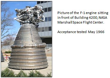
The J-2 rocket engine, developed by Rocketdyne and the NASA Marshall Space Flight Center, was qualified for flight in 1966. Between August 1966 and January 1970, 152 engines were produced. Between 1962 and 1971, some 3,000 engine tests were conducted. The J-2 engines were used for the second stage of the Saturn 1B vehicle and the second and third stages of the Saturn V vehicle. (Note that I wasn’t much involved in the original J-2 project considering that it was concluding just as I was figuring out that whole reading thing in First Grade. Remember Dick and Jane, Sally and Spot?)
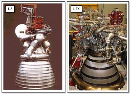
The most significant differences between these two engines can be found in their performance requirements. I suggest that these are most significant because it is these differences that lead directly to a majority of the physical design differences between these two engines.

That’s an increase in thrust level of over 25%. And the specific impulse increase is on the order of 6%. While that doesn’t sound like much, in the realm of rocket engines, given that the J-2 and the J-2X are using the same power cycle, it’s huge. It means that we’re pulling staged-combustion or expander cycle levels of performance from a gas generator engine. That’s really something special.
From requirements flows form. Or, as stated by architect Louis Sullivan (mentor to Frank Lloyd Wright): “Form follows function.” You don’t design and build a rocket engine a certain way because it’s neato. It’s designed to meet requirements that fulfill mission objectives. It’s not like a 1959 Cadillac where stuff was added just because it looked really cool (picture below courtesy of the Antique Automobile Club of America Museum in Hershey, PA).

In order to get that kind of boost in performance for J-2X, we had to do two fundamental things: (1) move more propellant mass through the engine, and (2) use that propellant more efficiently. To the first point, J-2X pumps into itself and expels out approximately 20% more propellant per second than did J-2. That translates into needing a whole lot more pumping power. Here’s a comparison of power requirements for the J-2 and J-2X pumps (as a point of reference, a typical NASCAR engine generates about 750 horsepower):

That’s between 80% and 90% more power for J-2X as compared to J-2. The reason that you need so much more is not only the need for greater flow, but also the need for more efficiency in usage is manifested as higher discharge pressures. I’ll explain this further below. But first, let’s talk about the hydrogen pump just because it’s an interesting story.
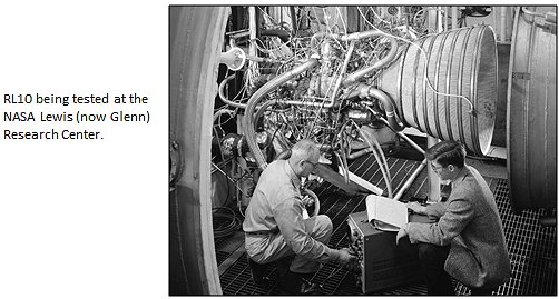
Back in the day, when J-2 was first being conceived of, the technology of how exactly to pump liquid hydrogen was still being developed. The RL10 engine existed already, but it was about 1/10th the size of J-2. Some work had been done with pumping hydrogen as part of the NERVA nuclear thermal propulsion development effort, but not everything learned there was widely distributed. This relative lack of information resulted in J-2 having a liquid hydrogen pump that was, in reality, an axial compressor. You see, the problem is that liquid hydrogen is so light that it kinda sorta acts as much like a gas as a liquid. I’ve heard it described as being like whipped cream but less sticky.

So, do you pump it like a liquid or like a gas? You typically use axial compressors for gases. That’s what you use in turbojets for airplanes. And you can get it to work with liquid hydrogen, as J-2 clearly demonstrated, but it’s not the best solution. One of the issues is that a compressor has some unfortunate stall characteristics where the effectiveness of the pump can plummet during the start transient. This is caused by what is known as the start oscillation that always happens in liquid hydrogen engines. Picture this: Prior to start, everything up to the valves that hold back the flow on the hydrogen side is chilled down to liquid temperatures (typically 36 to 39 degrees Fahrenheit above absolute zero). Then the valves open during start sequence and the liquid hydrogen suddenly comes into contact with relatively warm downstream metal. The result is similar to what happens if you sprinkle water into a hot frying pan. In other words, the liquid boils immediately upon contact. In a rocket engine this causes a transient “blockage” as this voluminous plug of newly formed hydrogen gas gets pushed through the system. In terms of the pump, this sudden “plug” downstream results in a transient, elevated pressure at the pump discharge and this can cause the pump to stall, especially if it’s an axial compressor. In order to overcome this effect, they had to precede the J-2 start sequence with several seconds of dumping of liquid hydrogen through the whole system to pre-chill the metal downstream of the valves.
Okay, so that’s not too much of a big deal, but it was a nuisance. By the end of the 1960’s, it was clear to most folks that the better way to pump liquid hydrogen was to use a centrifugal pump and that’s the way we’ve done it ever since (including on the J-2S engine, which was an experimental engine tested in the early 1970s as a follow-on to J-2). With a centrifugal pumps, you get to avoid the stall issues inherent with an axial compressor and you get a more compact, powerful machine. Which is good considering how much more power we need to pull out of the pump for J-2X.
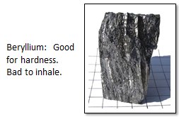
In addition to changing from axial to centrifugal, we had to make a number of other changes to the turbomachinery. In one place, we used to use on J-2 an Aluminum-Beryllium alloy. Well, you can’t use Beryllium anymore since it is considered too dangerous for the machinists working with the metal on the shop floor. In particular, Beryllium dust is toxic. And since we really like the guys working on the shop floor (as well as following the law), we had to go to another alloy. Also, we redesigned internal seal packages and rotor bearing supports using the most modern analysis and design tools and methods. In short, there’s not much in the turbomachinery, both fuel and oxidizer, that wasn’t reconsidered and redesigned to meet the imposed requirements.
Now, the other reason that we need 80% to 90% in addition to pumping 20% more “stuff,” is the fact that we had to get that stuff to higher pressures. Why? As discussed in a recent previous blog article, if we go to a higher combustion chamber pressure, then we can have a smaller throat and, with a smaller throat, we can have a larger expansion ratio without getting too out of hand with engine size. And, because of our extreme specific impulse requirement (remember: form follows function), we need that very large expansion ratio. So here are the top-level thrust chamber parameters:

The J-2 main combustion chamber was built from an array of tubes braze-welded together. When you needed the walls of that chamber to be actively cooled, this was the most common way to make combustion chambers “back in the day.” This is a fine method of construction, but it is kind of limited in terms of how much pressure it can contain. For the Space Shuttle Main Engine project in the early 1970’s, we needed the capability to handle a much higher chamber pressure and so we (i.e., Rocketdyne working in coordination with NASA) developed what is called a “channel-wall” construction method. So, to get the higher performance using the higher chamber pressure, we had to abandon the tube-wall construction method for the J-2X main combustion chamber and use a channel-wall main combustion chamber similar to the Space Shuttle Main Engine.
The main combustion chamber is on the top end of the scheme to get the larger expansion ratio. On the bottom end, we had to add a large nozzle extension. On the J-2, the nozzle consisted of another tube-wall construction. For J-2X, we have a tube-wall section that is actively cooled and then we have the radiation-cooled nozzle extension beyond that. The reason for transitioning is because the nozzle going out to a 92:1 expansion ratio has a diameter of nearly 10 feet and a tube-wall construction that large would be unreasonable heavy. In other words, from the vehicle perspective, the engine would be so heavy that its weight would offset any benefit from performance. The radiation-cooled nozzle extension is significantly lighter.
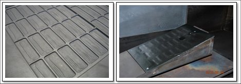
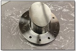
That make it sound easy, doesn’t it? If you want more performance, just strap on a big hunk of sheet metal and call it a nozzle extension. I wish that it were that easy. First, you need to figure out what material to use. Metal? Or maybe carbon composite? Plusses and minuses for both. Then you need to learn how to fabricate the thing light enough to be useful. And then you have to make it tough enough to survive the structural and thermal operating environments. In the pictures immediately above you can see a sample panel of how the J-2X nozzle extension is made and you can also see one of these samples sitting in a test facility where we blasted the panel with high velocity hot gases to partially simulate nozzle flow environments. The panel has a coating that enhances the radiation cooling so not only does the panel itself have to survive the environment, but so does the special coating.
Other things that we’re doing to get more performance out of the engine include the use of a higher density main injector and the use of supersonic injection of the turbine exhaust gases into the nozzle. When you talk about “injector density,” what you’re talking about is the number of individual injectors stuffed into a given space. Up to a point, the more injectors that you have, the better mixing you get, and, from that, the better performance you an extract from the combustion process. The picture below shows some testing that was done early on in the J-2X development effort to optimize the main injector density.
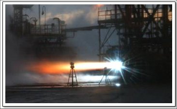
With regards to the turbine exhaust gas, on J-2 it was effectively dumped into the nozzle with the only intent being to not mess up the primary flow. For J-2X, we carefully designed the exhaust manifold and internal flow paths to get as even a distribution as possible around the nozzle and, from there, we are injecting it into the flow through mini throats at supersonic velocity. Here again we are extracting as much performance as we can given the simplicity of the power cycle.
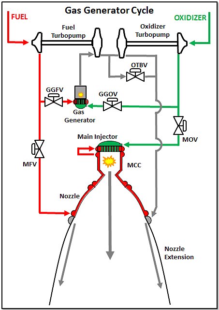
The next element of the engine to consider is the thing that creates the power that drives the turbines…that spins the pumps…that feeds the injectors…that fill the chamber…that makes thrust. In other words, I’m talking about the gas generator.

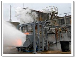
So, due to the increased power needs of the pumps, the gas generator has to flow twice as much propellant and at higher pressures through the turbines as compared to J-2. The temperatures are pretty much the same since this parameter is mostly limited by material properties of the spinning turbine components. In terms of “form following function” from a design and development perspective, these increased power requirements translated to the fact that gas generator used for J-2 was entirely inappropriate for J-2X. It just wouldn’t work. Rocketdyne had to design a new gas generator based upon work that they had done as part of the development of the RS-68 rocket engine (used on the Delta IV vehicle). In the past, I’ve shown some pictures and even video of the whole development test series that we conducted to validate the design of our gas generator. Below is a representative picture of our gas generator component test bed.
Something not captured in the table of performance requirements way up above is the bevy of requirements imposed on the J-2X in terms of health monitoring and controls functionality. These too resulted in differences between J-2 and J-2X.
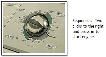
The J-2 engine had a sequencer to control the engine. Yes, it consisted of solid-state electronics, but other than that it was pretty much like the timer on your washing machine. The J-2X has an engine controller, which is a computer with embedded firmware and software that allows for a great deal of functionality in terms of engine control and system diagnostics. Some of these diagnostics we call redlines. These are specific limits that we place of measured parameters such that, should we break the limit, then we know that something bad has happened to the engine. The idea is to catch something bad before it turns into something potentially catastrophic. This is all part of the higher reliability and safety standards that have been applied to J-2X as compared to J-2.
The J-2X controller is composed of two independent channels such that if one fails, the other can take over. For critical measurements that inform the controller during engine operation, we actually take four separate measurements, compare them to make sure that they’re reasonable and good, and then use algorithms to perform the health checks. That’s one result of the imposition of more detailed requirements pertaining to reliability and safety. Along these same lines, we also have a number of design, construction, and workmanship standards that were applied to every aspect of the J-2X engine design, development, and fabrication. These standards, in combination with more evolved and advanced analysis tools, have, in a number of cases, further driven design changes away from heritage J-2 designs to what we’d call modern human-rated spaceflight hardware.
In an old J-2 manual, I found reference to a reliability value for that engine equivalent to 2,000 failures per one million missions. The requirement for J-2X is 800 failures per one million missions and, of those, only 200 can be “uncontained failures” meaning that the engine comes apart and potentially threatens other vehicle elements. So, all over the engine system we’re pushing more propellants, operating at higher pressures, generating more thrust, and squeezing out more performance efficiency, and we have to do this in a manner that results in an engine that has over twice as reliable as the heritage design. The result is an engine that is bigger and heavier than its historical antecedent:

So, in summary, here are the components that we had to change to meet J-2X requirements:
• Turbomachinery
• Main injector
• Main combustion chamber
• Nozzle
• Gas generator
• Added a nozzle extension
• Swapped the sequencer with a controller
What does that leave? Valves? Nope. Because of the higher flowrates and pressures, we had to drop the heritage designs for the valves and go to a design more akin to the Space Shuttle Main Engine. Ducts? Nope. Once you’ve changed all of these other things, you end up rearranging the connecting plumbing just as a matter of course. Even the flexible inlet ducts were changed slightly to accommodate more stringent design standards.
Form follows function; function flows from requirements; requirements flow from mission objectives. Different mission, different requirements, different function, and a different result. Thus, the J-2 and the J-2X share a name and share a heritage — in many ways the J-2 (and the J-2S) was the point of departure for the J-2X design — but the J-2X is truly its own engine. Lesson learned: Don’t assume too much from a name.
 It was late in the evening and a little chilly. Though we’d arrived at the control center before dusk, test preparations had dragged on so that now darkness had enveloped the center. The test stand stood out against the blackened sky like a battleship docked in the distance. Brian, my team lead at the time with whom I’d driven down from Huntsville, and I were standing outside in the control room in the parking lot. The radiation from the hydrogen flair stack off to our left warmed one side of our face as the breeze cooled the opposite cheek. The wailing of the final warning sirens drifted off and all that could be heard was the burning torch of the flair stack and, in the distance, the low surging and gushing of water being pumped into the flame bucket. We were a just a couple of hundred yards from the stand.
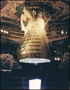 First, there is the flash and then, quickly, the wave of noise swallows you where you stand. Unless you are there, you cannot appreciate the volume of the sound. It is not mechanical exactly. It is certainly not musical. It is not a howl or a screech. It is, rather, a rumble through your chest and a shattering roar and rattle through your head. You think instinctively to yourself that something this primal, this terrible must be tearing the night asunder; it surely must be destructive, like a savage crack of thunder that continues on and on without yielding. You are deafened to everything else, deprived of hearing because of all that you hear. Yet before your eyes there is the small yet piercing brightness of the engine nozzle exit that can just be seen on what you know to be deck 5 of the stand and, to the right, there are flashes of orange flame stabbing into the billowing exhaust clouds mounting to ten stories high, tinged rusty in the fluctuating shadows. It is like a bomb exploding continuously for eight minutes and yet the amazing thing, in incongruent fact so difficult to grasp as you are trying to absorb and appreciate the sensation is that the whole event is controlled and contained. You cannot believe that so much raw power can be expressed by what is only a distant dot within your field of vision.


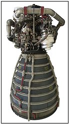 The name “RS-25” is, as I’ve mentioned in past articles, the generic name for the engine that everyone has known for years as the “SSME,” i.e., the Space Shuttle Main Engine. There is much to talk about the RS-25. Lots and lots of stuff. More stuff that I could possibly fit into a single article. Here are just some of the RS-25 topics that we’ll have to defer to future articles:
 have guessed, this is something that I wondered about many years ago as a pre-engineering spud. They seemed to be an awfully silly thing to build when you could just turn on the faucet and have water spurt out whenever you want. Ah, the wonderful simplicity of childhood logic: Things work just because they do and every day is Saturday.

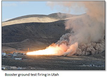


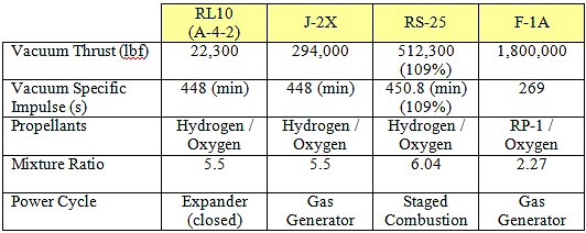
 For the SLS vehicle, the upper-stage engine is the rocket engine so near and dear to our hearts after several years of design and development and fabrication and assembly and test: J-2X. The core-stage engine is the RS-25. No, the RS-25 is not a brand new engine. Rather, it is the generic name for that workhorse of the last thirty years, the Space Shuttle Main Engine (SSME).
 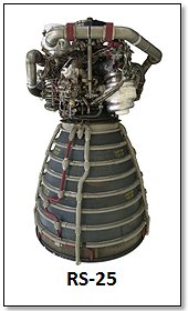 Thus, when you come to the end of a program and you have fourteen engines with remaining, usable life, then you’ve got one heck of a residual resource. In addition, there was one SSME assembled and ready to go, but it never made it to the test stand or the vehicle. So it’s brand new. And, on top of that, there were enough leftover pieces and parts lying around of flight-quality hardware to cobble together yet another engine. And, there’s more! (Yes, I feel like the late-night infomercial guy, “and if you call in the next 10 minutes you will get this special gift!”) There are also two development SSMEs. These are not new enough to fly, but they are useful for ground testing and issues resolution. That means that there are a total of sixteen RS-25 flight engines and two RS-25 development engines available to support the SLS Program.

