Inside the LEO Doghouse: Light My Fire!

This article is the second part of the story focused on how we start rocket engines.  In the last article, we discussed the matter of delivering propellants – oxidizer and fuel – into the combustion zone.  In this article, we will discuss how these propellants become fire and smoke (…or steam).  Of course, the musical reference for which you’re waiting ought to be based on the title of this article and the song by the Doors.  Right?  Well, with all due respect to The Lizard King, I would prefer to reference here the immortal writings of The Boss:

dark1
I will now be so bold as to translate Mr. Springsteen’s words into functional advice for rocket engines.  Sitting around and crying or worrying about the world are both passive, energy-draining activities.  The only way to start a fire is to add energy, e.g., a spark, to the situation.  He’s absolutely right.  And I would just bet that you never knew that The Boss was a rocket scientist.

In an article about combustion instabilities many months ago, I used the image below to illustrate a situation of limited stability.  The ball sitting on top of the hill will sit there forever unless or until something disturbs it.  Give it a little bump, i.e., an insertion of energy, and the whole scenario rapidly changes with the ball speeding down the hill.

ball2

This is also how I think about the process of ignition for typical, non-hypergolic (see previous article) propellants.  You can have fuel and oxidizer sitting around, intermixing, but until it gets that bump of an insertion of energy, there is no combustion.  No combustion; no high-energy gas production.  No high-energy gases; no propulsion.

Let’s start from the other end.  For a moment, think about a fire in your fireplace.  Once you’ve got a good fire up and going as in the picture below, you don’t have to re-start the fire each time that you add a log.  The existing fire sustains itself so that the energy produced by the combustion in one moment is sufficient to continue the fire into the next moment using additional fuel (the wood) and oxidizer (from the air).

fire1

This is generally the case for rocket propellants as well.  Once the fire is lit (i.e., once the ball is rolling downhill), the process is self-sustaining.  So, the whole issue about making a fire really does come down to the start of the process.

How many different ways can you start a fire?  One way is to use another fire.  Think about the folks running around the countryside with the Olympic torch before the games.  They use that torch to light another torch to light another torch, and on and on, all of the way until they light the big torch in the stadium.  Another way to start a fire is to use heat.  That, effectively, is how I lit a cigar the other evening.  I used friction to generate heat to ignite a match.  Then, holding the match like an Olympic torch, I used that fire to light the fuel of the cigar tobacco.  This model of a cascading series of larger and larger fires is used over and over in different forms.  Thus, when we talk about starting a fire, we often have to discuss not only the small initial energy bump, but then also the chain of events leading to the complete, steady state process.

So, first we have the initiation, or as The Boss said, “the spark.”  Off the top of my head, I can think of four ways that we’ve practically implemented on rocket engine systems to provide that initial energy boost and one other way that, to date, remains somewhat experimental.  There may be others, but these are the ones that are most obvious and frequently used in different forms.

The first method is exactly what The Boss calls for, an electrical spark.  In most cases when lighting liquid propellants directly, the components on rocket engines used to make electrical sparks are not a whole lot different than higher-energy, more robust, and more reliable versions of the spark plugs that you’ve got in your automobile.  They use a high-voltage electrical circuit to make a spark jump across a gap thereby exposing whatever is around that gap, namely vaporized propellants, to ionizing electrical energy.

spark1

The second method also uses electrical energy but in this case rather than making a spark, you use it to make heat.  Think about an incandescent light bulb (i.e., the bulbs rapidly becoming old fashioned these days).  The intent of the wire filament is to produce light.  And it does.  But is also produces heat.  What if you apply that heat directly to a combustible mixture?  Depending upon the mixture, that’s all you need.  I’ll explain more below when we talk about the cascade.

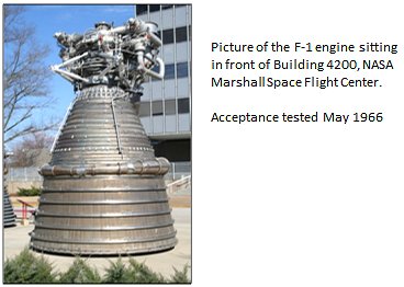
These first two methods rely on electrical energy and that’s always convenient since wires are easy to run.  While it’s true that the ultimate power source can be heavy for the vehicle (batteries for example), the rest of the system is relatively light and easy.  The third method for providing that initial energy bump is not quite so clean.  Rather than relying on transferring electrical energy into a chemical reaction, it uses a transfer of energy from one chemical reaction to kick off another chemical reaction.  In the previous article we discussed hypergolic propellants.  These are propellants that combust spontaneously when they come into contact with each other.  They don’t need any energy boost to start reacting.  Well, what if you had a fluid that did that when it came into contact with your primary fuel or primary oxidizer?  You could squirt in some of this spontaneously combusting stuff, light off a small bit of your fuel or oxidizer, and then the energy for that small fire could light off the rest of the propellants.  This is a common means for starting kerosene (also called RP-1) engines.  The massive F-1 engine used as part of the Saturn V vehicle was lit by a hypergolic ignition system for the main combustion chamber.  The most common hypergols for this purpose are triethylborane (a.k.a., triethylboron), triethylaluminum, or some mixture of the two.

triet1

The fourth and last method that I can think of for supplying that initial energy bump again starts with electricity, but instead of generating a localized spark or heat, you transform the electrical energy into a laser.  I will not even begin to pretend that I know much about lasers other than the fact that they can provide a very focused, directed beam of energy, photon energy in this case, to exactly where you want to put it.  You can use that energy to make heat for ignition or – and now I’m way beyond my knowledge base – you can tune the wavelength to excite the propellant molecules directly.  I have a friend in Germany who has experimented with using lasers for rocket engine ignition.  Thus far, I know of no fielded rocket systems where this ignition method is used (although I’ve been told that the Russians have demonstrated it on a full-scale engine), but it offers some very interesting possibilities.

laser1

So, we’re done, right?  After all, you’ve got your spark (or some other energy boost) so you’re lit and ready to go.  Well, not always.  For the most convenient ignition source, specifically the electrically-flavored ones, our bump in energy, our spark or heat, is usually very localized.  Rocket propellants are usually highly energetic and that’s why they’re rocket propellants.  But that also means that you have to light the fire well.  I struggle with how to explain this in a positive sense, so I’ll explain it in the negative, i.e., tell you what you do not what to do.

In your combustion zone, you do not want to ignite just one small space, i.e., one corner, and let the fire spread unevenly.  A fire on one side of a combustion zone but not the other could allow unburned propellants to momentarily “pool” in the one region.  This could lead to detonation and/or conflagration pressure waves bouncing around your chamber until everything evens out.  That can be extremely dangerous to the point of tearing apart the engine.  Or maybe, because of these pooled, unburnt propellants, you get mixture ratios that cause hot streaks.  Most practical combustion chambers are not built to accommodate stoichiometric or oxidizer-rich combustion (unless it is specifically an ox-rich preburner where it is should be very ox-rich to avoid this same issue).  A localized phenomenon of a slight ox-rich ignition could burn a hole right through a combustion chamber wall.  Or, if you’re talking about a gas generator or a preburner, you could get hot streaks that damage turbine components.  I have seen the kind of damage that can be done in a turbine due to ox-rich hot streaks for just fractions of a second.

turbine1

Ideally, what you want is for your propellants to arrive and, blammo, everything it lit.  That “blammo” can be difficult to achieve with a localized energy into like a spark or a small electrical heat source, especially for larger engines.  To overcome this issue, we turn back to the simple analogy of the fireplace.  There, we go from the localized effect of the match, to perhaps a ball or two of crumpled newspaper, to shavings or kindling, to larger sticks, to eventually the logs.  So there is a cascade of events from small and localized to large and generalized.  I will give you two examples of how we apply this concept in rocket engines.

The J-2X gas generator has a pyrotechnic ignition system.  It’s quite easy to tell people that we ignite the GG with little, solid propellant charges.  Okay, but is that the whole story?  No, it’s not.  The solid propellant charge (think about little Estes® rocket motors) is just the fire-lighting-the-fire end of the process.

process1

It all starts with electrical current running through an igniter wire.  The electrical resistance of the igniter wire causes heat as the current passes through.  That heat is enough energy to push what’s called the “pryogen” into ignition.  You can think of the pryogen as being like the stuff on the head of a match.  Other flammable substances are often used but the idea is still the same.  That little fire in the initiator ignites the solid propellant and the solid propellant then shoots hot gases into the GG during the engine start sequence to ignite the hydrogen and oxygen just as they arrive.  Pyrotechnic igniters like this are highly reliable.  If that electrical current arrives, everything beyond that is pure chemical chain reaction that produces a powerful blast of ignition energy.  On the negative side, such an igniter can only be used once.  I guess that you could inspect and refurbish elements of the piece, but considering the trauma of the process it experiences, it is easier and cheaper to simply replace the whole thing.

Another example of the concept of using an ignition cascade can be found on the J-2X in the form of the torch igniter used for the main injector.  Here’s an interesting little piece of history (as it’s been told to me).  The J-2 engine, back in the 1960’s was a pioneering effort.  While the RL10 was already flying, the use of hydrogen as a propellant was still something relatively novel.  For the J-2 main injector they developed a torch igniter system.  That system was later adopted and modified slightly for use as the ignition system for the Space Shuttle Main Engine main injector and both preburner injectors.  When we came to the development of J-2X, we started with our many years of successful experience with the SSME torch ignition system, made some modifications and, through a dedicated test program at the igniter level, effectively revalidated and expanded upon the pioneering efforts of the 1960’s.  It’s good to be part of another small step in that long and successful history.

process2

The torch igniter concept starts with an electrical spark from what really looks like your ordinary automobile spark plug.  But such a spark is very small, very localized.  So what you do is swirl into that localized area just a little hydrogen and oxygen.  This is the kindling.  The electrical potential across the gap of the spark plug causes the gasified propellants to ionize and become very hot, hot enough to start to spread the fire and, from that, thereby creating a flame front.  That flame is then directed into the combustion zone just as the rest of the propellants are reaching the injector.  The whole igniter system is effectively a torch ejecting a flame into the combustion zone.  In the J-2X (and in the SSME and in the J-2), the torch is right in the center of the injector face.

ssme

Okay, so there you have it, in two articles, how to get a liquid rocket engine up and going.  First, you have to get the propellants moving to the right places and, second, once they’re there, you’ve got to light the fire.  For large rocket engines, the whole process from the receipt of the start command from the vehicle until the engine is functioning at full power level takes anywhere from about three to six seconds.  During that time, pumps have to start spinning, valves have to open, propellants have to reach their destinations in the correct proportions, and the ignition source has to try to light the fire not too early and not too late.  It really is quite an orchestration of events across a brief period of time.  And the more complex the engine, the more difficult it is to get the orchestration right.

Looking into the database for SSME history, the very first test was conducted on 10 May 1975 with development engine #1 on test stand A1.  It was not until the forty-second test of the test series, nearly ten months later, that they eclipsed five seconds of firing duration and reached true mainstage operation.  So, it was not easy making that orchestration work.  Over the years, I’ve had the opportunity to meet and work with a handful of the folks who were there figuring out how to make the SSME work.  They were all very impressive engineers and thank goodness since we are still benefitting from their efforts.  And with that final historical note, we end this article with some more words of wisdom from The Boss:

boss1

J-2X Progress: Shaking up the Night

The first rocket engine test that I ever saw in person at the NASA Stennis Space Center in southern Mississippi occurred well over twenty years ago.  I’d already been doing test data analysis and power balance analysis in support of the Space Shuttle Main Engine (SSME) Project for some months.  I had made several data review presentations in front of then chief engineer (and rocket engine legend) Otto Goetz.  I could quote engine facts, statistics, and tell you all about how the SSME worked.  I’d even seen some videos of engine tests.  But it was not until I saw a test in person that I achieved the state that can only be described as awestruck.

WVBIt was late in the evening and a little chilly.  Though we’d arrived at the control center before dusk, test preparations had dragged on so that now darkness had enveloped the center.  The test stand stood out against the blackened sky like a battleship docked in the distance.  Brian, my team lead at the time with whom I’d driven down from Huntsville, and I were standing outside in the control room in the parking lot.  The radiation from the hydrogen flair stack off to our left warmed one side of our face as the breeze cooled the opposite cheek.  The wailing of the final warning sirens drifted off and all that could be heard was the burning torch of the flair stack and, in the distance, the low surging and gushing of water being pumped into the flame bucket.  We were a just a couple of hundred yards from the stand.

Then, the engine started.

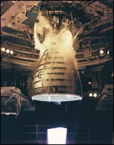
Picture1First, there is the flash and then, quickly, the wave of noise swallows you where you stand.  Unless you are there, you cannot appreciate the volume of the sound.  It is not mechanical exactly.  It is certainly not musical.  It is not a howl or a screech.  It is, rather, a rumble through your chest and a shattering roar and rattle through your head.  You think instinctively to yourself that something this primal, this terrible must be tearing the night asunder; it surely must be destructive, like a savage crack of thunder that continues on and on without yielding.  You are deafened to everything else, deprived of hearing because of all that you hear.  Yet before your eyes there is the small yet piercing brightness of the engine nozzle exit that can just be seen on what you know to be deck 5 of the stand and, to the right, there are flashes of orange flame stabbing into the billowing exhaust clouds mounting to ten stories high, tinged rusty in the fluctuating shadows.  It is like a bomb exploding continuously for eight minutes and yet the amazing thing, in incongruent fact so difficult to grasp as you are trying to absorb and appreciate the sensation is that the whole event is controlled and contained.  You cannot believe that so much raw power can be expressed by what is only a distant dot within your field of vision.

This is an experience that I wish everyone could have.  There are so many extraordinary feats of engineering all around us that we can appreciate and admire, but nothing for me has ever been as visceral as seeing an engine test, especially at night, with the nozzle open to the night air (and not buried in a diffuser).  No engine schematic or listing of characteristics or series of still pictures is an adequate substitute for the majesty of that controlled power.

Since that first test, I’ve seen any number of other engine tests including SSME (what we now call RS-25), a couple of other, smaller engines, and, of course, J-2X.  But it was not until the end of June of this year that I again had the opportunity to see a nighttime test on NASA SSC test stand A1.  This was J-2X E10002.  Below is the video, and it’s really cool, but I wish that you could have been there, standing beside me in the parking lot.  Listen carefully to the end of the recording and you’ll hear people cheering.  I was amongst the appreciative, awestruck chorus.


LEO Progress: RS-25 Adaptation

I love dictionaries (yes, I know, you’re shocked; shocked!).  I have several at home and at work including a two-volume abridged Oxford English Dictionary (OED) that was a wonderful gift from my mother several years ago. 


The definitions and word origin above comes from the OED on-line site.  Embedded within our language is so much condensed history and accumulated knowledge that it’s amazing.  While I have no doubt that this is true of every language, I only know my own to any significant degree.  Indeed, I’ve been babbling my own language for a long time now — forty-some years — but I can always pick up a dictionary and learn something new with just the flick of a page or two.  You really can’t say that about too many other things.

As the title for the article and the definitions above suggest, for this article we’re going to talk about “adaptation,” specifically about adaptation of the RS-25 engine.  As part of the Space Launch System Program, we are undertaking something a bit unusual for the world of rocket engines.  We are taking engines designed for one vehicle and finding a way to use them on another vehicle.  Now, this is not a completely unique circumstance.  The Soviets/Russians really were/are masters of this kind of thing.  But for us, it is not something that we do very often.  In terms of the big NASA program rocket engines, I can only think of the RL10 that was originally part of the Saturn I vehicle as an engine design that has had a long second and even third career on other vehicle systems.  The truth is that engines and vehicles are, for us, generally a matched set and the reason is that we just don’t frequently enough build that many of either.  Note that, technically speaking, we are also adapting the J-2X from a previous program, Constellation/Ares, but that’s obviously a bit different in scope and scale given where we are in the development cycle.

The name “RS-25” is, as I’ve mentioned in past articles, the generic name for the engine that everyone has known for years as the “SSME,” i.e., the Space Shuttle Main Engine.  There is much to talk about the RS-25.  Lots and lots of stuff.  More stuff that I could possibly fit into a single article.  Here are just some of the RS-25 topics that we’ll have to defer to future articles:

       •  History and evolution
       •  A tour of the schematic
       •  Engine control, performance, and capabilities

For this article, I want to just talk about the scope of work that will be necessary to adapt RS-25 to suit the Space Launch System Program. 


Clear Communication
The most significant thing that has to be done to the RS-25 to make suitable for the new program is that it has to be able to respond to and talk to vehicle.  Remember, the Space Shuttle was developed in the 1970s and first flown in the 1980s.  Yes, many things were updated over the years, but given the lightning-fast speed of computer evolution and development, it is not surprising that what RS-25 is carrying around a controller basically can’t communicate with the system being developed today for the SLS vehicle.  The SLS vehicle would say, “Commence purge sequence three,” and the engine would respond, “Like, hey dude, no duh, take a chill pill” and then do nothing (my lame imitation of 1980s slang as best I remember it).


But here are the neato things that we’ll be able to do: We can use almost all of the work now completed on the J-2X engine controller hardware to inform the new RS-25 controller and we can use the exact same basic software algorithms from the SSME.  Because the RS-25 has a different control scheme from the J-2X, we cannot use the exact controller unit design from J-2X, but we can use a lot of what we’ve learned over the past few years.  And, because we can directly port over the basic control algorithms, we don’t have to re-validate these vital pieces from the ground up.  We just have to validate their operation within the new controller.  That’s a huge savings.

This is work that is happening right now, as I’m typing.  Pratt & Whitney Rocketdyne, the RS-25 developer and manufacturer, is working together with Honeywell International, the electronic controller developer, on this activity.  Within the next couple of months, they will have progressed beyond the point of the critical design review for both the hardware and software. 

In the long term, it is our hope that we will evolve to the utopian plain of having one universal engine controller, a “common engine controller,” that can be easily fitted to any engine, past, present, or future.  Such a vision has in mind a standardization of methods and architecture such that we could largely minimize controller development efforts in the future to the accommodation of obsolescence issues.  The simple truth is that development work is always expensive.  It would be nice to avoid as much as that cost as possible.  With the new RS-25 controller, we’re getting pretty close to that kind of situation.

Under Pressure
Have you ever spent much time thinking about water towers?  As in, for instance, why are they towers in the first place?  As you might have guessed, this is something that I wondered about many years ago as a pre-engineering spud.  They seemed to be an awfully silly thing to build when you could just turn on the faucet and have water spurt out whenever you want.  Ah, the wonderful simplicity of childhood logic:  Things work just because they do and every day is Saturday.

The reason that you go to the trouble of sticking water way up in a tower is so that you have a reliable source of water pressure that can absorb the varying demands on the overall system.  In the background, you can have a little pump going “chug, chug, chug” twenty-four hours per day pushing water all of the way up there, but by having this large, reserve quantity always in the tower, the system can respond with sufficient pressure when, at six in the morning, everyone in town happens to turn on the shower at the same time to start their day.  The pressure comes from the elevation of tower, the height of the column of water from top to bottom.

On the Space Launch System vehicle we have something of a water tower situation except that, in this case, we’re dealing with liquid oxygen.  In the picture below, you can see roughly scaled images of the Space Shuttle and the Block 2 Space Launch System vehicle.  On both of these vehicles, the liquid oxygen tank is above the liquid hydrogen tank.  This means that for the very tall SLS vehicle, the top of oxygen tank is approximately fifty feet higher relative to the inlet to the engines (as illustrated).  This additional fifty feet of elevation translates to more pressure at the bottom just as if it were a taller water tower.  However, in this case liquid oxygen is heavier than water (meaning more pressure) and the SLS vehicle will be flying, sometimes, at accelerations much higher than a water tower sitting still in the Earth’s gravitational field.  Greater acceleration also amplifies the pressure seen by the engines at the bottom of the rocket.


“So what?” you’re saying to yourself as you read this.  After all, higher pressure is a good thing, right?  If you have more pressure at the inlet to the engine, then you don’t need as much pumping power.  So, life should be easier for the engines with this longer, taller configuration.  There are two reasons why this is not quite the case.

First, think about when the vehicle is sitting on the pad at the point of engine start.  The pumps aren’t spinning so all the pressure you’re dealing with is coming from the propellant feed system.  And now, simply, for the SLS vehicle it will be different than before.  One of the tricky things about a staged-combustion engine, in general, is that the start sequence (i.e., the sequence of opening valves, igniting combustion, getting turbopumps spun up) is touchy.  Given that the RS-25 has two separate pre-burners — and therefore three separate combustion zones — and four separate turbopumps, the RS-25 start sequence especially touchy.  You have to maintain a very careful balance of combustion mixture ratios that allow things to light robustly, but not too hot, and a careful balance of pressures throughout the system so as to keep the flow headed in the right direction and keep the slow build to full power level as smooth as possible.  We have an RS-25 start sequence that works for Space Shuttle.  Now, for the SLS vehicle, we will have to modify it to adapt to these new conditions.

The second issue to overcome with regards to the longer vehicle configuration and the liquid oxygen inlet conditions is due total range of pressures that the engines have to accommodate.  When sitting on the launch pad, you have the pressure generated by the acceleration of gravity.  During flight, as you’re burning up and expelling propellants, the vehicle is getting lighter and lighter and you’re accelerating faster and faster, you can reach the equivalent of three or four times the acceleration of gravity.  So that’s the top end pressure. 

On the low end, you have the effect of when the boosters burn out and are ejected at approximately two minutes into flight.  When this happens, the acceleration of the vehicle usually becomes less than the acceleration of gravity meaning that the propellant pressure at the bottom of the column of liquid oxygen can get pretty low.  Momentarily, the vehicle seems to hang, almost seemingly falling, despite the fact that the RS-25 engines continue to fire.  Pretty quickly, however, the process of picking up acceleration begins again.  (In the movie Apollo 13, they illustrated a similar effect with the separation of the first and second stages of Saturn V.  The astronauts are pushed back in their seats by the acceleration until, boom, first stage shutdown and separation happens and they’re effectively thrown forward.  With the Space Shuttle and the SLS vehicle, however, the return to acceleration is not as abrupt as it was on Saturn V where they show the astronauts slammed back into their seats with the lighting of the second stage.)  The point is that the RS-25 has to accommodate a very wide range of inlet pressures while maintaining a set thrust level and engine mixture ratio.  While this has always been the case for the SSME/RS-25, the longer SLS vehicle configuration simply exacerbates the situation.

You’ll note that I’ve not talked about the liquid hydrogen here.  That’s because, as I’ve mentioned in the past, liquid hydrogen is very, very light.  Think of fat-free, artificial whipped cream.  Yes, the top of the hydrogen tank is much higher, but due to the lightness of the liquid, it doesn’t make much difference at the engine inlet even when the vehicle is accelerating at several times the acceleration of gravity.

Some Like it…Insulated
Look again at the pictorial comparison of the Space Shuttle and the Space Launch System vehicles shown above.  Do you see where the SSME/RS-25 engines are relative to the big boosters on the sides of the vehicles?  On the Space Shuttle, the engines were on the Orbiter and they were forward of the booster nozzles.  On the SLS vehicle, there is no Orbiter so the engines are right on the bottom of the tanks and their exit planes line up with the booster nozzle exit planes.  In short, the engines are now closer to those great big, loud, powerful, and HOT boosters.  We are in the process now of determining whether this poses any thermal environments issues for the RS-25.  Thus far, based upon analyses to date, there do not appear to be any thermal issues that cannot be obviated through the judicious use of insulation.

Other environments also have to be checked such as the dynamic loads transmitted to the engine through the vehicle or the acoustic loads or whatever else is different for this vehicle.  The point is not that all of these environments are necessarily worse than what they were on the Space Shuttle.  It is only that they all need to be checked to make sure that our previous certification of the engine is still valid for all of these considerations.

The Tropic of Exploration
So those are the three most obvious and primary pieces of the RS-25 adaptation puzzle: a new engine controller, dealing with different propellant inlet conditions, and understanding the new vehicle and mission environments.  Each of these pieces carries with it analysis and testing and the appropriate documentation so there is plenty of work scope to accomplish.  We are extremely lucky to be starting with an engine of such extraordinary pedigree, performance, and flexibility. 

Henry Miller once said, “Whatever there be of progress in life comes not through adaptation but through daring.”  It is our intent to prove Mr. Miller wrong in this case.  We will make progress by using the adaptation of RS-25 to enable the daring of our exploration mission.

Inside The J-2X Doghouse: Performance Measurement, Part 2 of 2

In the last article, we talked about the measurement of propellant flow during a test.  Propellant is the stuff we put into the rocket engine.  What we get out of the rocket engine is thrust.  We get propulsion.  Or, in the immortal words of Salt-n-Pepa, 1987, we get push… “Push it real good.”

But how do you measure “push,” or in other words, force?  The simple answer can be found through one of the most frightening household appliances any of us own:  The dreaded bathroom scale…

A bathroom scale works by pushing back at your weight when you stand on it.  Your weight is a force caused by your body mass and the Earth’s characteristic acceleration of gravity.  The scale pushes back with a spring system but deflects slightly under the load.  The scale is then measuring the deflection allowed by the springs at the equilibrium where the spring force exactly counteracts your weight.  More weight pushing down results in more deflection to the equilibrium point and that thereby results in a bigger reading (i.e., think: the Monday after Thanksgiving).

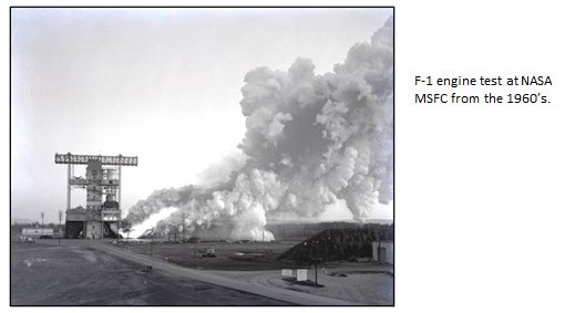
The way that we measure rocket engine thrust is basically the same thing except that instead of measuring something between zero and — as in the bathroom scale picture above — 300 pounds, we’re measuring hundreds of thousands of pounds of force.  Or, in the case of very large engines like the F-1 or the RD-170, we’re measuring over a million pounds of thrust.  That requires a system just a bit more rugged even if the principles remain the same.  What we use rather than bathroom scale and springs are things called “load cells.”  Below is an example of a generic load cell design:

The gray object with the funky cut through it is a metal piece.  As you can imagine, when forces are applied as shown, that slot on the right-hand side will tend to close slightly.  In turn, that would cause the metal on the left-hand side to stretch slightly as the whole thing bends a very little amount.  We measure that slight stretching of the metal on the left-hand side with a strain gauge bonded to the surface of the metal.  A strain gauge is a small electrical device that changes resistance when stretched.  Using an electrical circuit known as a Wheatstone Bridge, we measure small changes in electrical resistance caused by the slight deformations of the load cell.  The amount of stretch can be astonishingly small and yet good strain gauges and good electrical interpretation of the output can yield very accurate data.  The load cell is then calibrated using a known applied load and measuring the resulting strain (i.e., metal stretch).  You now have a more rugged version of a bathroom scale.  Apply a load, get a reading, and, ta-da, you’ve measured push.

Actual load cells used for rocket engines can take different forms from the generic cell shown here.  Any way that you can get an applied load to result in a slight, measureable stretching of metal (while obviously avoiding yielding or buckling) is a valid load cell design.

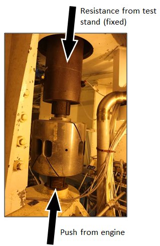
Above is a picture of a vertical load cell arrangement on test stand A-2 at the NASA Stennis Space Center, where we’ve been testing J-2X development engine E10001.  There are two pieces in series.  The bottom piece, the big chunk of metal with a bunch of crazy holes and slashing cuts through it, is called a “flexure,” which, to me, seems to be a silly name since it doesn’t look very flexible at all.  What it does, however, is effectively make sure that the load entering the load cell is properly directed through the intended vector.  Any skewing of the input off from the intended axis and your results could be erroneous.  The brown cylindrical thing above the flexure is the actual load cell.  You can see the strain gauge wires coming out of it that are fed into the data acquisition system.  This two-piece combination is effectively analogous to a spring in your bathroom scale.

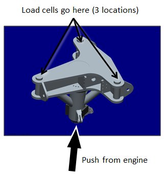
The next item to discuss is how you put load cells into the structure of the test stand so that they can do their job.  On a bathroom scale, the thing that you step onto is essentially a platform “floating” above the base.  It has to be free to move so that the springs can compress honestly.  If there was some interference with this movement, then the reading would be wrong.  The same is true on the test stand when measuring engine thrust.  It is necessary to use a free-floating platform.  The picture below is a drawing of the platform used on test stand A-2.

The engine has a single input point as shown — the gimbal bearing that we’ve discussed before in previous articles — and there are three load cells above the platform.  This is not the only possible way to do it.  Other test stands use a rectangular pattern of four cells.  Or, if it’s a smaller system, you might be able to use just a single load cell.  The important point is that the load cells are in between the pushing engine and the resisting test stand.  Put into the structure of the test stand, and viewed from the side as in the picture below, you can see the whole stack up.  On the bottom is where you attach the engine.  In the middle is the platform into which the engine pushes.  And then the platform is connected to the structure of the stand through the load cells.  The structure of the stand has to be strong enough to absorb the thrust of the engine without distorting.  It has to be fixed (the mythical “immovable object” from physics class).  So, as you can imagine, when you’re talking about hundreds of thousands or even millions of pounds of force, the test stand structure is pretty darn stout.  We usually refer to the primary structure responsible for resisting the force of the engine as the “thrust take-out” structure. 

A final subject to mention is that matter of tares.  Tares are corrections to measured data.  For example, when you step on the bathroom scale and you’re dressed, do you subtract off an estimate for the weight of your clothing and your shoes?  If so, then you’re making a correction for a particular tare.  Of course, you have to do this accurately (honestly).  If I assume that my clothes and shoes are made of lead, for instance, then I can declare that I weigh the same as when Salt-n-Pepa were releasing their first albums.  But that’s not quite the truth.  Getting your tares correct is important for interpreting your data correctly.

When measuring rocket engine thrust you have lots and lots of corrections to the raw data that you measure with your load cells.  This is because, in truth, the gimbal bearing is not the only connection between the engine and the test stand.  While you’d really like to have that perfectly free-floating platform situation, you’ve got to have, for example, propellant feedlines hooked up to the engine.  Flexible bellows are built into the line so that they’re not completely stiff and thereby interfering with the movement of the platform, but they still absorb some of the thrust load and, therefore, make the raw thrust reading skewed.  There are a number of other such corrections that need to be made such that the whole calculation process related to tares can get a bit cumbersome with all its many pieces, but nobody ever said that developing rocket engines was supposed to be easy, right?

Now, between this article and the previous one, you have a good idea of how we get basic performance data from rocket engine testing and also the necessary configuration of the test stands that allow us to gather this information.  The smoke and fire and rumbling roar of an engine test is all very impressive, but for us Datadogs, it’s the data that matters most.  We get lots and lots of data from every test, but propellant flow rates and engine thrust are the most important in terms of understanding how an engine fits into a vehicle and a mission.

Inside The J-2X Doghouse: Beyond the Gas Generator Cycle

Okay, I admit it: I’m a sucker for the Olympics.  I watch with rapt attention to sporting events that I would otherwise never consider viewing other than under the once-every-four-years heading of the Olympics.  Why is that?  Perhaps that is somehow a measure of my shallowness as a sports fan.  Nevertheless, I was truly on the edge of my seat watching the women’s team archery semi-finals and finals.  Great drama.  Wonderful competitors.  Exceptional skills.  Bravo ladies!

Another thing that I find fascinating about the Olympics is the fact that it brings together such a broad range of people.  No, I’m not going to trail off in a chorus of Kumbayah.  You simply cannot deny, however, that during the opening ceremonies you see people of every possible color and shade, from every corner of the planet, straight hair, curly hair, black hair, blonde hair, red hair, eye colors to fill a rainbow, and most startlingly, such an amazing collection of body types.  These are all world-class athletes and yet they’re often so different from each other.  I like seeing the six-foot-seven volleyball player walking next to the four-foot-ten gymnast.  I like seeing the contrast of the marathoner and the shot-putter.  We’re all the same species, but, my goodness, we come in an amazing array of shapes and sizes and various accoutrements.

The Pivot to Topic
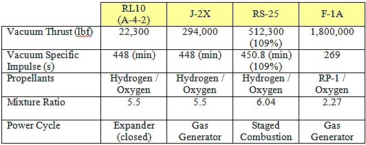
Rocket engines, too, come in an array of shapes and sizes and various accoutrements (…I bet that you were wondering when or how I’d turn the conversation on topic).  I know that this is a blog dedicated nominally to J-2X development, but I think that it’s important to understand where the J-2X fits in this family of rocket engines.  So, let’s start with a table of top-level engine parameters:

Note that is list is nowhere close to being comprehensive.  There are lots and lots of rocket engines out there including those currently in development or in production and many that have been retired (like the F-1A in the table).  And if you open the window a little wider to include engines originating from beyond our shores, then you’ve got many more Soviet/Russian, European, Japanese, and Chinese engines to consider.  All I want to do here is expose you to some basic yet significant differences between this small set of examples.  Interestingly, if you can understand these few engines, then you can understand most of rest of the ones out there as variations on these basic themes.

Please allow me to introduce you to the engines listed in the table. 
• Of course, the J-2X needs no further explanation for anyone who reads this blog regularly. 
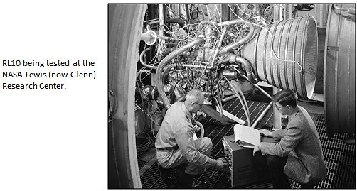
• The RL10 is a small engine that has been the product of Pratt & Whitney since the late 1950’s.  Over the past sixty years it’s evolved and matured.  It was actually used on a NASA vehicle back in the 1960’s, the Saturn I launch vehicle upper stage (S-IV).  Today it’s used, in different variants, as an upper stage and in-space engine for both the Atlas V and Delta IV launch vehicles. 
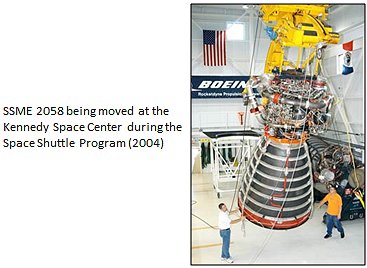
• The RS-25 is another name for the Space Shuttle Main Engine (SSME).  The development of the SSME began with research efforts in the late 1960’s, using a great deal of knowledge gathered from the development of the original J-2, and it was first tested in 1975 and first flew on STS-1 in 1981.  The RS-25 engine is now designated to be the core stage engine for the next generation of launch vehicles under the Space Launch System (SLS) Program. 
• The F-1A was an upgraded version of the F-1 engine that powered the first stage (S-IC) of the mighty Saturn V launch vehicle that first took man to the Moon.  The F-1A was a more powerful version of the F-1 with a handful of design changes intended to make it cheaper yet more operable and safe.

The Key is in the Power
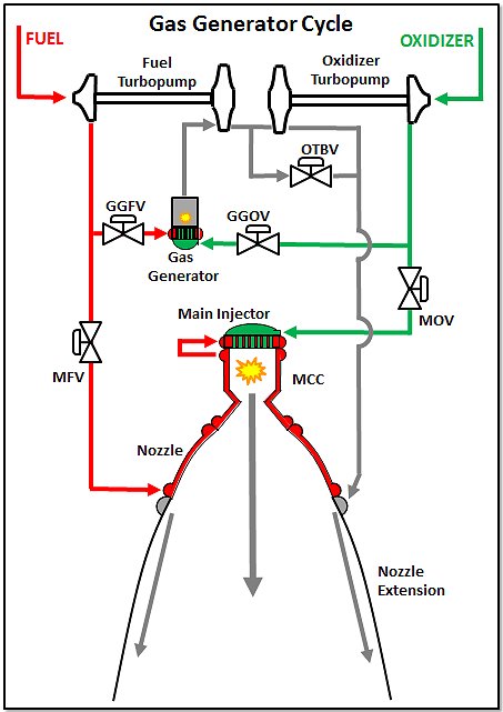
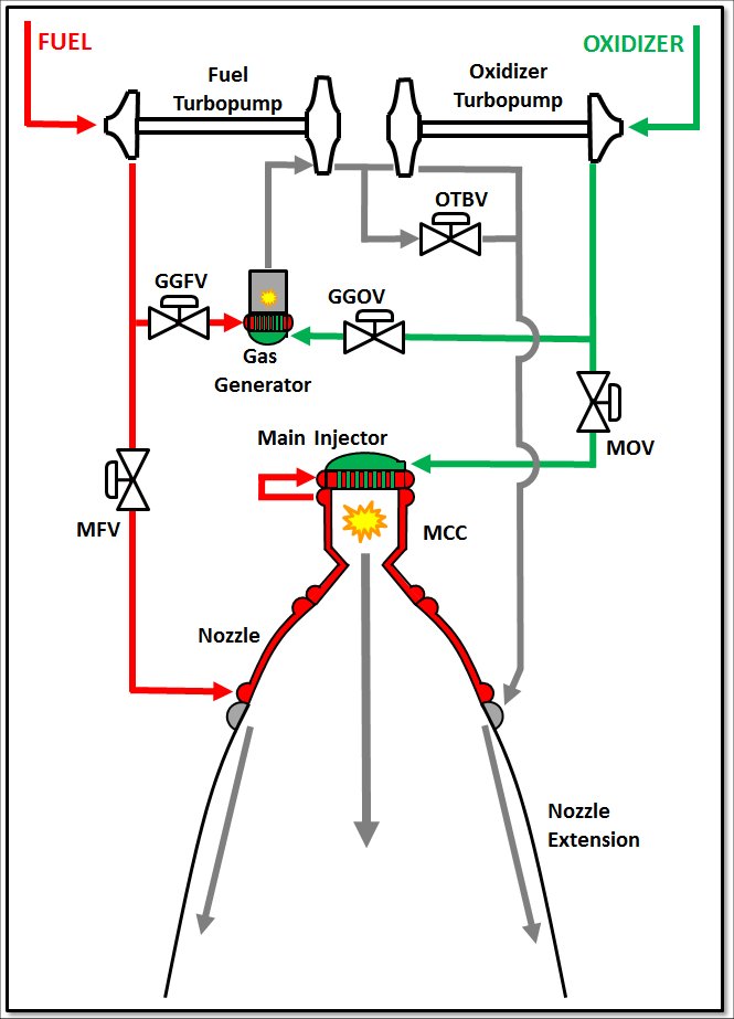
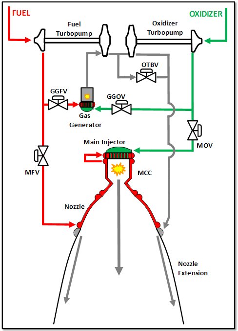
In a blog article here over a year and a half ago, I introduced you to the gas generator cycle engine.  The key philosophical point discussed in that article about what makes a rocket engine an engine is the fact that it feeds and runs itself.  It does this by finding a means for providing power to the pumps that move the propellants.  The origin for this power is the key to any rocket engine cycle.  In a gas generator engine, this power is generated by having a separate little burner that makes high-temperature gases to run turbines that makes the pumps work.  Below is a schematic for such a system.  You’ve seen this schematic before and it is very much like J-2X.

Where:
      MCC = Main Combustion Chamber
      GG = Gas Generator
      MFV = Main Fuel Valve
      MOV = Main Oxidizer Valve
      GGFV = Gas Generator Fuel Valve
      GGOV = Gas Generator Oxidizer Valve
      OTBV = Oxidizer Turbine Bypass Valve

Behold Now Behemoth
The F-1A power cycle is similar to the gas generator cycle shown above in that it is still a gas generator cycle, but rather than two separate turbopump units, there was only a single (huge) unit that contained both pumps.  So, a single turbine was used to power both pumps rather than having two separate turbines like J-2X.  Going back to the table, you will see that the F-1A was different from the J-2X also in the fact that the propellants were different.  The J-2X uses hydrogen for fuel and the F-1A used RP-1 (FYI, RP-1 stands for “rocket propellant #1” and is actually just highly purified, high quality kerosene).  The chief difference between hydrogen and kerosene is chemistry.  A hydrogen-fuel engine will get higher specific impulse than a kerosene-fuel engine but kerosene engines have the distinct advantage of being able to generate more thrust for a given engine size.  With a kerosene engine, you are simply throwing overboard more massive, high-velocity propellants in the form of combustion products.  Hydrogen is light and efficient from a “gas mileage” perspective but kerosene gets you lots and lots of oomph.  That’s why you typically use it for a first stage application like on the Saturn V vehicle.  You want to have lots of oomph to get off the ground.  Later, on the upper stages, you can better use the greater gas mileage afforded by hydrogen.

Note, however, that you could theoretically build a hydrogen engine as large as the F-1A in terms of thrust.  The RS-68 (also a gas generator cycle engine) on the Delta IV vehicle puts out around three quarters of a million pounds-force thrust so that’s pretty big.  Also, back in the 1960’s, there was conceptual design work performed on an enormous hydrogen fuel, gas generator cycle engine called the M-1.  On paper, that behemoth put out 1.5 million pounds-force of thrust just like the F-1 on the Saturn V.  But that project was abandoned and here’s why: hydrogen is very, very light so if you want to carry any appreciable amount, you need to have truly huge tanks.  Huge tanks mean huge stages.  Huge means heavy.  Eventually it becomes a game of diminishing returns at the vehicle level.

What this discussion of J-2X and F-1A (and RS-68 and even M-1) shows you is the extreme versatility of the gas generator cycle.  It can be used with nearly any reasonable propellant combination and it can be scaled from pretty darn small to absolutely enormous.

Shaving with Occam’s Razor
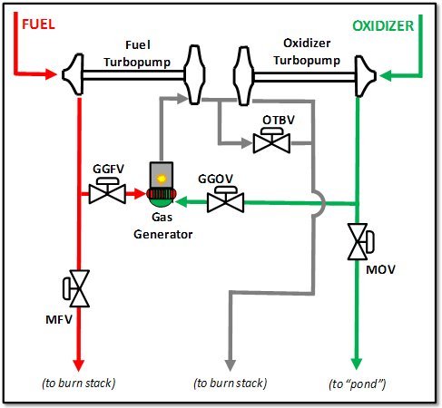
Occam’s Razor is the notion that one should proceed with simplicity until greater complexity is necessary.  Along these lines, I will introduce you to a simpler engine cycle: the expander cycle.  For this engine cycle, you do not use a gas generator to drive your turbine(s) so you don’t have a second, separate combustion zone apart from the main combustion chamber.  That makes everything simpler.  Instead, you use only the heat gathered in the cooling the thrust chamber assembly (i.e., the main combustion chamber walls and that portion of the nozzle regeneratively cooled).  See the schematic below.

See?  I got rid of not just the gas generator but also the two valves that fed the gas generator.  That’s huge in terms of simplification.  And whenever you can make an engine simpler you’ve usually made it cheaper and more reliable just because you have fewer things to build and fewer things that could break.  Cool!

Here, however, is the problem: How much power do you really have just from the fluid cooling the walls?  The answer can be found by looking at the table and seeing, for example, the RL10 thrust output is less than one-tenth of J-2X.  You just can’t pull that much energy through the walls.  There have been attempts to increase heat transfer by various means including making the main combustion chamber longer than typical so that you have more heat transfer area or even by adding nubs or ridges onto the wall to gather up more heat.  Using the longer chamber notion, the European Space Agency is working on an engine called the Vinci that almost doubles the thrust output from the RL10, but getting much further beyond that is darn tough.  Also note that hydrogen is a wonderful coolant based upon its thermodynamic properties.  Being a wonderful coolant means that it picks up a lot of heat.  It is difficult to imagine using the expander cycle engine with another fuel beside hydrogen (though maybe methane might work … haven’t examined it). 

On the plus side, in addition to the simplicity, what the cycle shown offers is what is called a “closed cycle” meaning that no propellants are thrown overboard other than through the main injector.  In a gas generator cycle engine, after the gas generator combustion gases pass through the turbine(s), it’s dumped into the nozzle (or, in other schemes, dumped overboard in other ways).  Any propellants or combustion products that do not exit the rocket engine through the main injector and through the main combustion chamber throat represent an intrinsic loss in performance.  “But,” you’ll say, “the specific impulse for the RL10 and the J-2X in the table are the same.”  Well, that’s a little bit of apples and oranges because it’s based upon the nozzle expansion ratio.  Another model of the RL10, the B-2, has a much larger nozzle extension and the vacuum specific impulse for that model is over 462 seconds (minimum).  The European Vinci engine that I mentioned above has a projected vacuum specific impulse of about 465 seconds.  Those are darn impressive numbers that make the mouths of in-space stage and mission designers drool.

A couple of final notes about the expander cycle engine.  First, the RL10 is not quite like the schematic shown.  It only has one turbine with one pump driven directly and the other pump driven through a gear box.  Thus, the OTBV goes away (making it even simpler!).  Second, there are versions of the expander cycle engine concept that are not closed cycles.  In these versions, you dump the turbine drive gas overboard in a manner similar to what you do in a gas generator cycle.  You are still using the heat from the chamber walls to drive the turbine(s), so it’s still an expander, but with an overboard dump you can also leverage a larger pressure ratio across the turbine(s) and thereby get a bit more oomph out of the cycle.  You sacrifice a bit of performance for more oomph.  The Japanese LE-5B engine is an open expander cycle engine like this (also called an “expander bleed” cycle).

“We do these things not because they are easy…”
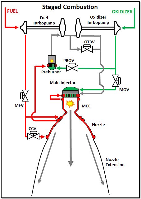
So, you’ve seen the incredibly versatile gas generator cycle engine.  And, you’ve seen the simple yet limited expander cycle engine.  So what do you do if you say, “The heck with it, I want the Corvette”?  What if you want a closed cycle, high performance engine not limited to lower thrust levels and you’re willing to accept consequent greater complexity?  The answer is staged combustion.  Below is a simplistic schematic for a staged-combustion engine.

Where:
      CCV = Coolant-Control Valve
      PBOV = Preburner Oxidizer Valve

In a staged combustion cycle engine, we rename the gas generator and call it the “preburner.”  The biggest difference between a gas generator cycle and a staged combustion cycle is what you do with the turbine exhaust gases.  In a gas generator cycle, the turbine exhaust gases effectively get dumped overboard.  In a staged combustion cycle, the turbine exhaust gases get fed back into the main injector and get “burned again.”  This is possible since the combustion in the preburner is off from stoichiometric conditions, meaning that in addition to combustion products you also have lots of leftover propellant (either fuel or oxidizer depending on the scheme). The leftover propellants from the turbine exhaust then become part of the mix of propellants in the main combustion chamber.

That sounds simple, right?  It’s just a twist on the gas generator cycle theme, right?  Well, there are larger implications.  First, think about the pressure drops through the system.  On a gas generator cycle engine, the pressure in the gas generator can be lower than the main chamber.  After all, the downstream side of the turbine(s) is effectively ambient, external conditions.  In a staged combustion cycle, the preburner pressure has to be substantially higher than the main chamber pressure sitting downstream of the turbine(s) or you don’t get enough flow to power the turbine(s).  Insufficient turbine power and the cycle doesn’t work.  So, in general, a staged-combustion cycle engine has higher system pressures than a gas-generator cycle engine of comparable size.  Next, think about starting the system.  In a gas generator cycle engine, the two combustion zones are effectively disconnected.  In a staged combustion cycle engine, the two combustion zones are on either side of the turbine(s) so there is effectively communication between these two zones.  Now, try to imagine getting these two combustion zones ignited and up to pressure and the turbine(s) spun up to speed in an orchestrated manner during the start sequence.  It ain’t easy.

So, what do you get for this complexity and higher operating conditions?  Well, you get a closed cycle, high performance, and high thrust engine design choice.  The RS-25 (SSME) is the American example of such an engine.  If you put a higher expansion ratio nozzle on the RS-25, just as with the RL10 discussion, the specific impulse value would be as much as ten seconds higher than J-2X.  However, if you go out and find a schematic of an SSME, what you’ll see is a heck of a lot more complexity than even I’ve shown in my simplified sketch.  Because the pressures are so high, there are actually four separate turbopumps and a boost pump in the SSME.  The design relies on putting pumps in series to achieve the necessary pressures and fluid flow rates through system.  And, the SSME has not one but two separate preburners, one for the high pressure fuel turbopump and one for the high pressure oxidizer turbopump.  It’s a very complex engine, but it has extraordinary capabilities.

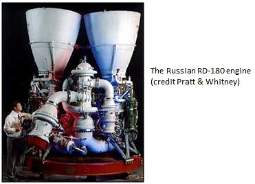
The RS-25 (SSME) is a staged combustion cycle engine with hydrogen as the fuel.  The preburners are run fuel-rich such that the generated gases contain excess hydrogen for injection in the main chamber.  Back in the days of the Soviet Union, they developed a whole series of staged combustion cycle engines that instead used kerosene as the fuel.  In these engines, the preburner is run oxidizer-rich so that the gases run through the turbines and then through the main injector have excess oxidizer to be used for final combustion in the chamber.  The Russian-supplied RD-180 that is currently used for the Atlas V launch vehicle is an example of such an engine.  It too is an extremely complex, high pressure, and high performance engine.

So, staged combustion cycle engines are not easy.  Their complexity and operating conditions suggest, generically, greater expense and lower reliability.  But if you can make the trade-off between high performance and the adverse issues, then they can function quite impressively.  Nearly thirty years of Space Shuttle flights are an indisputable demonstration of this fact.

Just One Bolt
Can you imagine opening a hardware store and selling just one kind of bolt?  That would be it.  One brand.  One diameter.  One length.  And just one bin full of identical versions of this one bolt in your store.  It sounds really kind of stupid.  The unavoidable truth is that you need different bolts for different applications.  It’s kind of like trying to imagine telling the Olympic gymnastics team that they now had to play basketball and the basketball players to do gymnastics.  I don’t know about you, but I’d love to see Lebron James have a go at the pommel horse.

Well, over the last fifty-plus years, we’ve developed different rocket engines and rocket engine concepts for a variety of different applications.  Just one design does not fit all applications.  Each design has advantages and disadvantages.  If you can understand the basics of what I’ve discussed in this article, however, then you will have a fundamental understanding of at least 90% of the engines spanning that fifty-plus years of history.  And that, in turn, might help you better appreciate why one bolt is chosen over another or why, for example, shot-putters tend to be a bit more beefy than cyclists. 


Welcome to the J-2X Doghouse: All a Matter of Balance — and Power

One of the most important analytical tools used in development of a rocket engine is called a “power balance.”  A power balance is, stated simply, a simulation of the steady-state, internal conditions and functioning of the engine.  It can, on one extreme, be accomplished with a spreadsheet or, on the other extreme, take the form of a complex computer program with hundreds of theoretical calculations bolstered by dozens upon dozens of embedded, empirical relationships customized for a particular hardware configuration.  But first of all, let’s talk about what a power balance is from a purely conceptual point of view.  You start with a schematic of the engine:


Where:
       MCC = Main Combustion Chamber
      GG = Gas Generator
      MFV = Main Fuel Valve
      MOV = Main Oxidizer Valve
      GGFV = Gas Generator Fuel Valve
      GGOV = Gas Generator Oxidizer Valve
      OTBV = Oxidizer Turbine Bypass Valve

Next, you break down these pieces of the engine, the components, into descriptions with regards to how they relate to power, pressure, and temperature:

  • Pumps:  Convert shaft power into fluid power in the form of elevated pressure
  • Turbines:  Extract power from the turbine drive gases and converts it to shaft power
  • Gas Generator and Main Combustion Chamber:  Generate power from combustion
  • This power is in the form of elevated temperature (combustion = fire = hot)
  • Ducts, Valves, and Injectors:  Control fluid movement in order to get propellants and combustion products where they need to be, i.e., plumbing.  Each of these items reduces pressure in the fluids flowing through them
  • Cooling Jackets:  Here too pressure is lost as the fluid flows through the cooling passages, but temperatures are elevated as heat carried away (i.e., as cooling takes place)

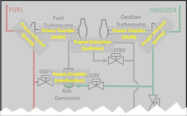
Thus, in terms of the most significant power considerations, here is what is going on with the rocket engine:

You’ll note that all of the power stuff happening in the engine is happening up on the top portion of the original schematic (and I’ve chopped away everything else).  In other words, the major power transfer stuff happening in the components that make up what we call our “powerpack” testing.  See?  That’s why and that’s where the name comes from.  Pretty clever, huh?  The whole idea is to get power to pumps so that they can makes lots and lots of fluid pressure so that they can push lots and lots of propellants through the system and into the combustion chamber.  That’s the whole point of the rocket engine, push stuff to the combustion chamber to make thrust. 

So, how much pressure do you need?  That’s a matter of how much stuff you’ve got to push the propellants through and how much pressure you want in the chamber at the end.  I sometimes think of it like that great old board game Monopoly ®.  You pass “Go” and get $200.  Remember that? 


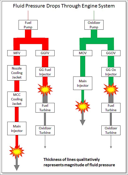
Well, in a rocket engine, your pump is “Go” and at that point you get an allotment of pressure.  Then, as the fluid goes through the system, from component to component — ducts, valves, cooling jackets, injectors — you have to pay rent in the form of a loss of pressure.  That’s like landing on the various squares around the board.  Paying all that rent is just fine.  You can’t really avoid it.  But you have to make sure that you save enough money to stay at the hotel on Boardwalk in the end without going bankrupt.  In other words, you need to get your propellants into the chamber at the residual pressure that you desire.  Here’s a representation of this pressure management process within the J-2X on both the fuel side and on the oxidizer side:


The explosion-looking symbols in that diagram represent combustion zones.  One is the gas generator, where you make the power to drive the pumps, and the other is, of course, the main combustion chamber, where you make your thrust.  The gray lines represent combustion products coming out of those combustion zones.

One last question that needs to be considered is this: How much combustion chamber pressure do you want (and/or need)?  In other words, when your propellants arrive at the main combustion zone, at what residual pressure do you want that combustion to take place?  Sounds like a simple question, right?  Well, of course, you want it to happen at the “optimal” pressure.  But what does that mean?  That is not an easy question to answer.  In terms of energy release, within certain bounds, the chamber pressure does not much matter (or, at most, it’s a secondary factor).  What it really comes down to, believe it or not, is engine size and weight and a handful of manufacturing considerations. 

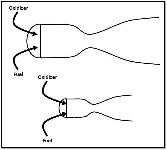
In the drawing above, I have tried to show two combustion chamber and nozzle combinations where the one on top has a throat diameter and nozzle exit diameter twice as large as the respective measurements in the lower version.  Thus, both engines using these combustion chambers and nozzles would have the same ratio of nozzle exits area to throat area.  It’s just that the one on the top would have a throat with four times as much area (area being proportional to the square of the diameter).  Would it surprise you to learn that these two engines could generate the same thrust if the one on the bottom had four times as much chamber pressure as compared to the one on top?  Yep, it’s true.  If the top engine has, say, 500 psi (pounds per square inch) chamber pressure and the bottom one has 2,000 psi, then these two rockets are — to first order estimates — operating at the same performance level. 

What does that mean?  That means that you could have a great big, bulky rocket engine or you could have a small, “tight” one.  It would seem that the small one feels more efficient except that with that high chamber pressure you have to generate all that extra pressure in your pumps.  That takes a lot of pump power and therefore turbine power.  And containing all of that pressure throughout the engine system means thicker walls on your ducts and valves and everything else.  Thicker walls mean heavier pieces.  So maybe that “tight” engine is really more wasteful.  So instead, maybe the big bulky engine sounds like a good idea since it’s easier on your turbopumps.  Except then you realize that it’s too big to fit on your vehicle and, by the way, that monstrously big nozzle weighs a ton and nobody has machining tools large enough to produce the thing.  So maybe the bulky one isn’t right either.  Blah, blah, blah…  It’s enough to give you a headache!  But those kinds of discussions back and forth are what are known as trade studies and they are the foundation for what your engine will eventually become.  There is rarely a simple, obvious answer since everything has impacts on everything else.

So, how does all of this get back to the power balance?  Well, you take all of those notions discussed above and start applying the following:

  • Calculations that describe how much energy is released by the combustion of your propellants.
  • Calculations that relate pump speed and pump design features to fluid pressure increases.
  • Calculations that relate turbine-drive gas conditions and turbine design features to power extraction.
  • Calculations that describe pressure losses for fluid flowing through ducts, valves, cooling jackets, and injectors.
  • Calculations that relate fluid flow and fluid conditions to heat transfer processes in cooling jackets

Once you have all of these relationships, then you can perform a power balance.  You use your power balance to inform your trade studies.  Bigger or smaller?  Faster or slower?  You just have to realize in using it that you can’t get anything for free.  The power that you generate in your gas generator uses up some of your propellants (for a gas generator cycle engine) so they can’t go through main injector with the purpose of generating thrust.  You cannot perfectly extract the power from the turbine drive gases.  And, you also cannot pump with perfect efficiency.  These considerations all have to be taken into account in your calculations.  But the result will be an analytical model that can tell you the pressure and temperature of the propellants throughout their journey through the engine.  It will tell you shaft speeds of the turbopumps.  And it will give you overall performance of your rocket engine.


So, let’s say that you’ve been given the job of designing an engine from scratch.  You have a thrust requirement and a specific impulse requirement.  Let’s say, further, that you know what your propellants are supposed to be and let’s even go so far to say that you’ve been told that it ought to be a gas generator cycle engine.  Okay, so now what do you do?

Here’s one approach (…one of many, many possible):

  • Pick a chamber pressure.
  • Because of your thrust requirement and specific impulse requirement, you can start with a pretty good guess as to your propellant flow rates.
  • Next, generate your schematic layout of the engine and the various components and piece together your simulation of the system.
  • Then, figure out how much pressure your pumps need to generate and, therefore, how much power you need your gas generator to create.
  • Balance that pump power needed with turbine power to be extracted; you’ve now set your gas generator conditions.
  • Based upon how much propellant that you’re “losing” down the gas generator / turbine drive leg, you can figure out how much nozzle expansion ratio you need to get to your specific impulse requirement.
  • You’ll probably go around a bit in circles with the previous few steps — also known as iterating — until you get a completely self-consistent set of answers (It’s essentially a process of making educated guesses, seeing if everything balances out, making new guesses based upon any lack of balance, and again seeing if everything balances.  With a good solution scheme, you’ll eventually arrive at a place where all your guesses work and your system is balanced.)
  • You now have a rocket engine design.

But, is it what you want?  Can you build it?  Does it fit with the vehicle?  Will it be too heavy?  Are the component performance factors within reasonable expectations (i.e., rules of thumb carried around by the various component experts)?  Is the design close enough to a legacy design so that you might be able to leverage previous, related experience?  Or, perhaps, is the design all so new and different that the necessary development program will be quite extensive (and therefore expensive)?  It may be that there are a whole bunch of reasons why your design, frankly, stinks so you need to go through the whole process again.  In the end, after several cycles through, you almost never come up with a design that makes everyone happy from every perspective, but you come up with one that is sufficient, acceptable, and reasonable.  So that’s the design that you go and design, develop, and test.

Hopefully, I’ve shown you that a power balance, an analytical simulation of the internal workings of an engine, is an integral tool in the conceptual design of a rocket engine.  Once you’ve got some general idea of some key parameters you need, the power balance fills in the details, sets the necessary parameters for your turbopumps, captures your fluid splits and conditions, and establishes the general sizing for your main combustion chamber and nozzle.  It uses physics and physics-based empirical relationships — combining the disciplines of fluid dynamics, heat transfer, combustion science, and hardware mechanics — for all of the major components of the engine to balance the power generated against the power used and, in so doing, describes conditions throughout the engine.

(This, by the way, is my favorite kind of analytical modeling simply because it combines so many different disciplines and yields such a broad and useful tool.  I was lucky enough to be assigned to power balance modeling activities for the Space Shuttle Main Engine when I started working.  And that experience has informed everything else I’ve done for the last 20+ years.)

Welcome to the J-2X Doghouse: Old Dogs, New Tricks

A couple of articles back, I asked the following question:

“The whole orange-flame thing is not something I entirely understand…Any ideas from anyone else?”

I was talking about the flame stack during a night test at the NASA Stennis Space Center.  It was a legitimate question.  Combustion chemistry is really not my specialty.  Lots of things are not my specialty.  Try as I might, I’ve found that I can’t know everything about everything.  Indeed, considering the many brilliant and knowledgeable people with whom I have the privilege of working here at NASA, I’ve come to accept the conclusion that there is a lot more stuff to know than can ever be learned.  But that can never stop you from learning something new.  And so I have with this.

In response to my blog question, we received a number of comments on the blog and those are posted.  Thank you for your inputs and interest. 

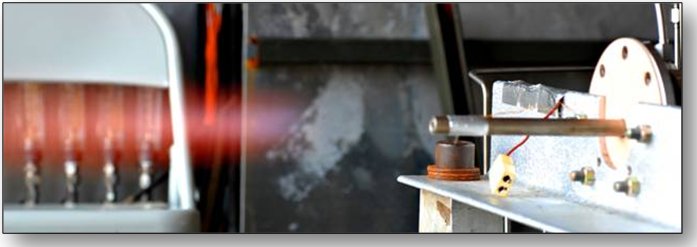
However, behind the scenes (so to speak), a coworker of mine, Robin Osborne, who does have experience with this kind of stuff read the blog and starting poking around amongst her notes and amongst her fellow experts in the field of flame spectroscopy.  Below is a picture taken of igniter testing at MSFC using a gaseous hydrogen-oxygen mixture.  Here too you can see a red-orange flame although it takes a distance for that colored portion to show itself.


According to Dr. Robert Pitz from Vanderbilt University, “Pure hydrogen (with no sodium) — air flames will glow red in a dark room due to the water vapor emission lines.”  Both Dr. Joseph Wehrmeyer working in support of the Air Force and Richard Eskridge from NASA concur, noting that water vapor generates an orange-red-infrared continuum in such flames.  However, all of these individuals also noted that there is a strong orange coloration in such flames due to sodium contamination within the hydrogen.  The sodium is present as sodium hydride within the liquid hydrogen which decomposes at high temperatures to generate the vibrant color.   The sodium contamination is a byproduct of how large, industrial quantities of hydrogen are made for uses such as, for example, flying the Space Shuttle.  Dr. Christopher Dobbin of NASA noted that in the 1990 timeframe he was engaged in an analysis of the flame plumes ejecting from the Space Shuttle Main Engines (SSME).  He said, “The (time) average sodium concentration we measured in the SSME exit plane was 0.091 parts per billion.”  That doesn’t sound like much, and it’s not enough to impact engine performance or operation, but it’s still enough to measure based upon spectral analysis of the plume.  Another possible contaminant, according to Richard Eskridge, is potassium and that can further contribute red emissions.

So, there you go.  It’s a matter of water vapor at the right temperature and pressure (and therefore density) and a couple of key contaminants in the fuel.  It’s “common knowledge” around here amongst us Datadogs that the plume of a Lox/Hydrogen rocket engine is clear.  But that’s not entirely correct.  It’s nearly clear.  It still has the characteristic red-orange tint, but it’s at a density where the emission is too low to see.  On the other hand, for the flame stacks at the test facility — the origin of this whole discussion — we’re talking combustion at atmospheric pressure so the water vapor products are denser as are the relative contamination levels since it’s a fuel-rich environment.  And that’s why they show up at those brilliant colors in the nighttime pictures.

See, even old Datadogs can learn new tricks.  Thank you to everyone who added their two cents, but especially to Robin Osborne for her inputs and insight.

J-2X Progress: Getting All Spun Up

If you go back through the J-2X Development Blog articles, you’ll find one about the “Burp Test” that we conducted last July on J-2X development engine E10001.  In that case, we ran a very short test where we activated the helium spin start system and we ignited the main chamber, very briefly, before we shut down the whole thing.  Well, here we are about six months later and we’re doing the equivalent thing on the J-2X PowerPack Assembly 2 (PPA2).  Here is a video of the test:


Testing at night is always so much more dramatic.

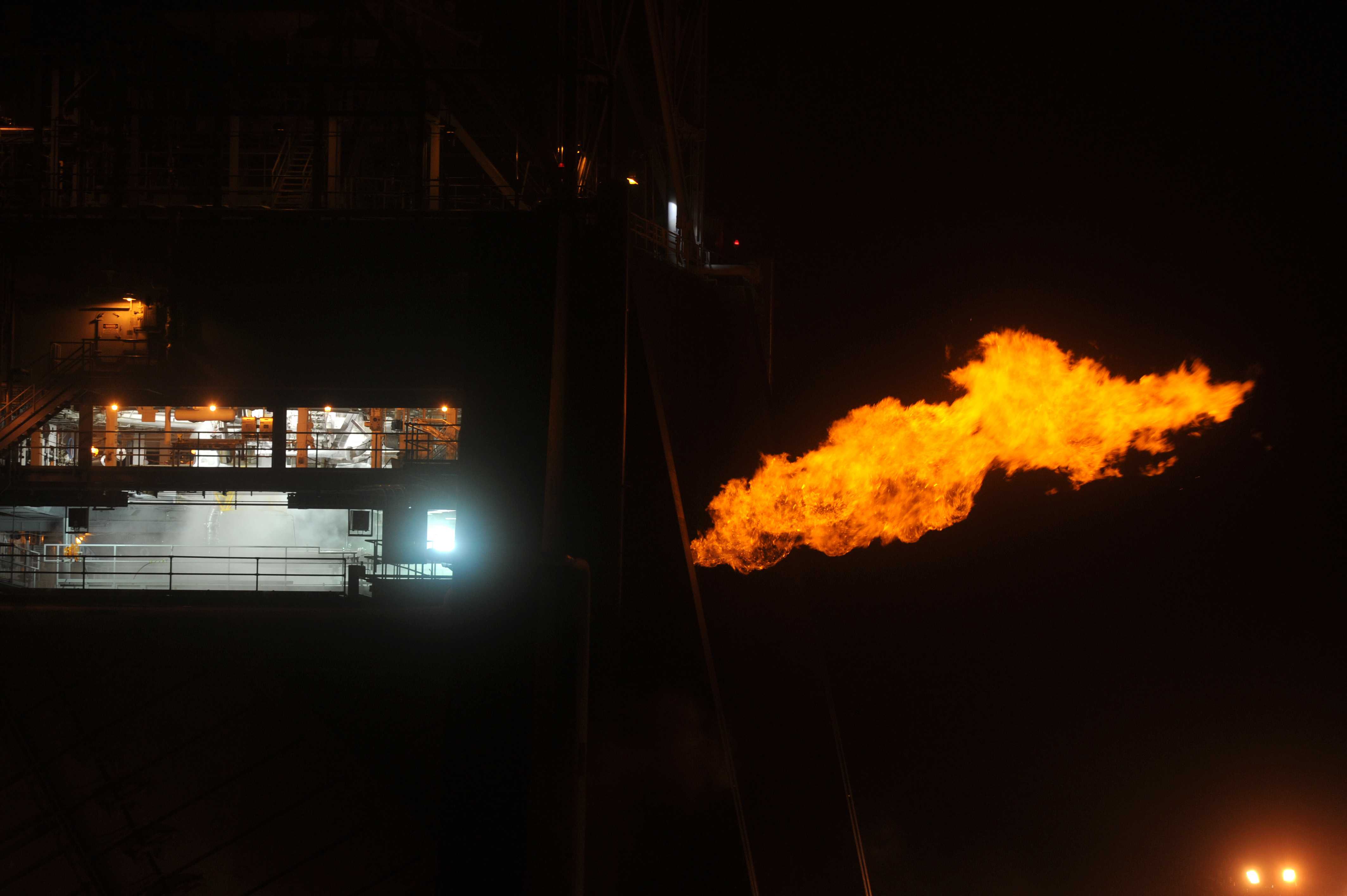
For the PPA2, there is no main chamber to light, so this entire test was primarily focused on exercising the helium spin start system.  The flames that you see are from flare stacks necessary to get rid of the hydrogen used in the test.  Remember, the PPA2 is primarily a test article for turbomachinery and the gas-generator turbine-drive system.  It doesn’t make thrust.  All of that hydrogen that gets pumped by the fuel turbopump has to be disposed of in a controlled manner other than in the production of thrust.  So, we burn it off.  The liquid oxygen is disposed of as well, but it doesn’t require anything quite so gaudy as flare stacks.

Interestingly, when hydrogen burns, it usually burns clear.  The whole orange-flame thing is not something I entirely understand, but it always looks that way at night.  There’s some propane in the flame used as kind of like a pilot light, but not enough to cause that much color.  It could be that burning hydrogen at such a low mixture ratio (i.e., not enough oxygen immediately available so you get afterburning effects) is the cause of this as compared to the usual white hot rocket engine exhaust.  It’s also possible that it’s stuff in the air or somehow water vapor effects, or disassociation effects, but I honestly don’t know.  Any ideas from anyone else?  I’d love to hear some theories.  I do know that if you’re standing anywhere where you can see the flame, you can feel the heat radiating from it.  It’s quite an impressive experience.

Beyond exercising the helium spin start system, what this test also did is prove out the test stand subsystems, the test stand and test article control systems, demonstrates that the gobs and gobs of instrumentation is hooked up, working properly, and feeding back reasonable data, and that the proper procedures are in place to conduct a safe test.  Every facet listed is a big, big deal and has to work in conjunction with everything else. 

The folks at the Stennis Space Center — civil service, support contractors, and prime contractors alike — all deserve kudos for pulling this off successfully and, really, with minimal technical issues.  Way to go guys!  This test is yet another in a long string of demonstrations of the power of collaboration and the overall dedication and excellence of the J-2X team.  We’re now ready to step into the meat of the test series and start putting the hardware through its paces.  This is going to be exciting!  Go J-2X!

J-2X Progress: The Next Phase for E10001

In January, the Chinese people celebrated their traditional New Year and formally initiated the year of the Dragon.  I was born in the year of the Dragon (it comes up every twelve years) and I started thinking about previous Dragon years and where I was when they occurred.  My first year of the Dragon after my birth happened to be the 200th birthday of our great country and I was starting sixth grade.  My second year of the Dragon was the year that I got married so that was kind of important to me on a personal level.  My third year of the Dragon was the year that I started working for NASA after spending a decade working for defense and space industry contractors.  It is interesting looking at one’s life in such a series of widely separated snapshots.  Things move on.


The same is true for J-2X.  Last year was momentous for our project.  We assembled and tested our first development engine, E10001.  We celebrated and received well-deserved (if I do say so myself) kudos and pats on the back.  But now things move on and the life of our good friend E10001 enters its next phase.  And the next phase for E10001 involves changes to its nozzle configuration.  So, before I tell you specifically what we’re doing to E10001, we need to discuss how a supersonic nozzle works.

Below is a schematic of what, on a rocket engine, would be called the thrust chamber assembly or the main injector plus main combustion chamber plus the nozzle.  Within the realm of compressible flow this is known as a convergent-divergent nozzle, or as a “de Laval nozzle” after a late 19th-century Swedish engineer, Gustaf de Laval, who pioneered using such shapes as part of steam engines […and you woke up this morning not realizing that you’d learn something historical today!].  How it works is simple.  Fluid flows from high pressure at the head end on the left towards the low pressure at the exhaust on the right.  In between, the flow area of the “pipe” in which the fluid flows is manipulated to accelerate the fluid.  The most narrow point in the flow is called the throat.  Fluid flow to the left, upstream, of the throat is subsonic, i.e., traveling at less than the speed of sound.  If the ratio of “high” to “low” pressure at the two ends is large enough, then fluid flow to the right, downstream, of the throat is supersonic, i.e., traveling at greater than the speed of sound.  Under such conditions, the velocity at the throat itself is exactly that of the speed of sound.  In other words, the fluid is traveling at “Mach 1” at the throat [the term named for Ernst Mach, an Austrian scientist and philosopher also from the late 19th century].  Oh, and all of this only works if your “fluid” is compressible, or in other words a gas like air or, in a rocket, combustion products.


How and why this happens gets a little heavy on the thermodynamics, so please just trust me for now.  But the really neato thing that Mr. De Laval learned when playing with convergent-divergent nozzles like this is that: (1) for subsonic flow, as the flow area gets smaller, the flow velocity goes up, (2) for supersonic flow, as the flow area gets larger, the flow velocity goes up.  In other words, they act the opposite of each other.  For a rocket, this is absolutely fantastic since the whole idea of a rocket is to fling stuff out the back end at very, very high velocity and this cool device accomplishes that with just a little bit of creative geometry. 

Okay, with me so far?

Then, here’s another thing to think about regarding supersonic flow: You can’t shout upstream.  Sound is nothing more than pressure waves traveling through a fluid.  A gas has a characteristic speed at which pressure waves are conveyed within it.  That, then, is the speed of sound.  So, if the gas is traveling at greater than the speed of sound, then pressure waves cannot travel upstream.  Think of it this way: imagine yourself to be a gas molecule.  Normally, when traveling less than the speed of sound, you can receive signals from all directions.  Your motion can be impacted by pressure waves both upstream and downstream of where you sit at any given time.  However, now imagine that you are that gas molecule hurtling along in a supersonic flow.  Now, because you’re traveling faster than the ability of pressure waves to get back upstream, you can have no idea what’s going on downstream.  You’re flying along blindly. 

Thus, the bottom line is that once the ratio of high and low pressures are sufficient to cause this situation of supersonic flow in the divergent portion of the nozzle (a term that we use is that the throat is “choked”), then the nozzle flow is the nozzle flow.  In other words, it is largely independent of what happens beyond the exit plane.  Largely, but not entirely.  I’ll explain below.  Hold on.

Next, we’re going to talk about the Bernoulli Equation [developed by an 18th-century father and son team of Swiss professors Johann and Daniel Bernoulli].  No, we’re not going to do any math.  All that we have to do is understand the concept of the Bernoulli Equation and how it relates to the flow in the divergent portion of our nozzle.  Here it is:  Absent other factors, when fluid is accelerated, its pressure drops.  You can think of this in terms of energy.  Pressure is like stored energy, as in electrical energy in a battery.  Velocity is active energy, as in electrical energy spinning a fan.  Absent any other input or output, when you show more active energy (velocity), you then have less stored energy (pressure). 

Just for fun, here are some pictures of the men I’ve mentioned so far.  Oh, and I tossed in a friend of Daniel Bernoulli’s named Leonhard Euler.  Anyone who knows anything about mathematics or fluid dynamics knows all about Mr. Euler.  He was truly a genius on par with Sir Issac Newton.  (BTW, I kinda like the white, powdered wig thing the Bernoulli guys had going there.  Maybe I’ll adopt it myself…)


Back to the topic at hand.  Where do we stand once we combine compressible fluid flow through the divergent portion of a de Laval nozzle, traveling at speed greater than Mach 1 (meaning that pressure waves cannot travel upstream), and with the application of the Bernoulli Equation and the effect on pressure?  I will attempt to show you in a picture…


So, if I make my nozzle longer and longer and longer, with a larger and larger exit size, my exhausting gas goes faster and faster and faster.  Again, that’s why rocket engines have big divergent nozzles.  Ta-da!  But, there are limits.  There always are.  Nothing is free.

The first limit is weight.  As your nozzle gets bigger and bigger, your nozzle structure gets heavier and heavier.  As some point, any gain in engine performance is offset by the loss of vehicle performance because your engine is too heavy to lift.

The second limit is due to what’s on the other side of the exit plane.  What’s outside the nozzle is, well, the ambient environment.  If you’re sitting at the NASA Kennedy Space Center in Florida, where we usually launch our rockets, the ambient conditions are known as “sea level” conditions, meaning that the atmospheric pressure averages about 14.7 pounds per square inch.  On the other hand, if you’re floating around in space and in orbit around the earth, then your ambient conditions are, to a pretty good approximation, a vacuum, meaning 0.0 pounds per square inch pressure. 

What happens if you’re that gas molecule hurtling along in the flow at supersonic velocity down the nozzle and then you’re suddenly flung into ambient conditions?  Well, if you’re in the main part of the flow, not much.  You eventually slow down through a series of oblique shocks external to the nozzle.  As I said above, if you’re moving supersonically within the nozzle, then you’re not affected by what’s downstream.  But what if you’re not in the main flow but instead along the wall?  Here’s a secret: The flow along the wall is slower than the main, core flow.  Indeed, exactly at the wall, in the limit, the velocity is zero.  That changes things.

So, exactly at the wall, the velocity is zero, and just fractions of an inch into the flow the velocity is supersonic.  This transition zone is known as the “boundary layer” and the fluid dynamics complexity here can be nearly mind boggling and it has to do with viscous friction between the fluid and the wall.  But the important point is that there is a thin layer that is not supersonic.  Below is a typical textbook-like representation of boundary layer flow. 


Remember when I said that what happens beyond the exit plane largely doesn’t affect the fluid flow in the nozzle?  The boundary layer is the exception.  Because the flow here is subsonic, pressure conditions downstream can influence things upstream.  And here is the source of the other limit on your nozzle size. 

If the ambient pressure is much, much higher than the pressure of the nozzle flow, then this pressure can slow up the subsonic portion along the wall.  If you slow it up enough, you can make the boundary layer thicker and thicker until it’s no longer just fractions of an inch thick.  Having a thick boundary layer means that your nozzle is not flowing “full.”  The flow can become “detached” from the wall and such a situation is inherently unstable.  All around the nozzle, in local pockets, the boundary can grow and collapse and grow again causing localized pressure variations.  Shock waves start bouncing around.  Then the nozzle structure itself, usually not built very stiff so that it doesn’t weigh too much, starts to respond to these local pressure variations and shock waves and it wobbles and ripples and buckles.  To put is more succinctly, if your nozzle expands the rocket exhaust flow too much for the ambient conditions, you have an “over-expanded” condition and this can literally tear the nozzle apart.  Below is a picture that tells the story of the impact of ambient pressure on nozzle flow.


Now, finally, we’ll get back to J-2X E10001.

For all of the tests conducted to date, the nozzle that we’ve tested on E10001 has had an expansion ratio of 35 to 1, meaning that the area of the exit plane is thirty-five time larger than the area of the throat.  With this kind of expansion ratio for this engine, the nozzle flow is not over expanded.  The nozzle “flows full” at sea level conditions like those seen at the NASA Stennis Space Center (SSC) where we test the engines and all is good.  But the J-2X is intended to be an upper stage engine in flight, meaning that when it fires during the mission, it will be at over 100,000 feet in the altitude where the ambient pressure is much less than sea level conditions.  Because of that, we designed the engine to use a larger nozzle, get more performance from greater exit velocity, and not over expand the exhaust flow at THOSE conditions way up in the upper atmosphere, practically in space.

But then how do we test it?  If we have a nozzle that flows full at altitude, but does not flow full (i.e., it’s over expanded) at sea level, then how do we perform a test showing that the nozzle works?  We can’t exactly build a test stand at 100,000 feet in the sky.  Instead, we make the test stand simulate these high-altitude conditions.  Below is a picture of NASA SSC test stand A-2.  What you see there in the middle, the big tube several stories tall surrounded by structures, is the passive diffuser.


The diffuser, combined with a clam-shell enclosure structure around the bottom portion of the engine, uses Bernoulli effects (see, they come into play again!) such that when the engine is firing, it does so into an ambient environment that “appears” to be like that at high altitude.  By doing this, for the next phase of J-2X E10001 development, we will be able to do testing with a nozzle extended to an expansion ratio of 59 to 1.  That is one step closer to the ultimate flight configuration for the J-2X as part of the exploration mission and therefore one step closer to fulfilling that mission.  It takes a bit of explaining to understand why all this is necessary, but the bottom line truly is that we are getting closer and closer to our exploration goals.

So, enjoy come on along with us to celebrate the Year of the Dragon with the generation of lots of smoke and fire from the J-2X.  It’s going to be fun.  But first, maybe a few traditional Chinese New Year’s treats…


J-2X Progress: A New Star on Our Horizon

J-2X Progress:  A New Star on Our Horizon

For weeks and weeks (or months and months really), we’ve been going on and on about the star of our J-2X project, development engine E10001.  And there is every reason to focus much of our attention on this first example of our new engine.  It has really put on one a heck of a show, generating oodles of data, and we’re far from being finished with it.  


So, E10001 is unquestionably a star.  Beyond this, however, we have other potential stars waiting in the wings.  I would liken this situation to “American Idol” except that I’ve never actually seen that show and, further, all of our test articles are not in competition with each other.  Indeed, the whole point of a coordinated and integrated development plan is for all of the test plans and test articles to complement each other.  One big star that will soon be making an important contribution is called “PowerPack Assembly 2” (or “PPA2”).  Okay, you’re saying to yourself:  I know what an engine is, but what is a “powerpack assembly”?  And, why is this number two?  Good questions.  We’ll start with the first one…

A powerpack assembly — or simply a “powerpack” — is a subset of the total engine.  Specifically, it is the engine minus the thrust chamber assembly (i.e., the main injector, main combustion chamber, and nozzle/nozzle extension).  About a year ago, I wrote an article here in the J-2X development blog talking about what a gas-generator cycle rocket engine looks like.  The schematic of that cycle is shown below for reference and comparison:


Where:
MCC = Main Combustion Chamber
GG = Gas Generator
MFV = Main Fuel Valve
MOV = Main Oxidizer Valve
GGFV = Gas Generator Fuel Valve
GGOV = Gas Generator Oxidizer Valve
OTBV = Oxidizer Turbine Bypass Valve

The lines and arrows in red denote fuel (hydrogen) flow; the green lines and arrows denote oxidizer (oxygen) flow; and the gray lines and arrows denote the flow of combustion products.  Using the same abbreviations and same color schemes, here is the schematic for a gas-generator cycle powerpack:


See?  As I said, you simply pull off the whole thrust chamber assembly and there you go: powerpack.  If you think of the thrust chamber assembly as what you use to make thrust, then the powerpack portion of the engine is what you use to feed the thrust chamber assembly.  In other words, to be particular, it’s the gas generator, the turbopumps, and the full set of major control valves…plus, of course, the lines and ducts that connect everything together.

What this configuration allows you to do, far more so than the complete engine configuration, is “play games” with turbomachinery conditions and operations.  And here’s why.  On the full engine configuration, you have to feed the thrust chamber assembly a pretty steady diet of fuel and oxidizer.  If you deviate too far, things get too hot or too cold or you get too much pressure in the chamber or too little.  The thrust chamber assembly is a wonderful piece of equipment, astonishingly robust when functioning in their normal regimes, but it’s basically static and, to be honest, a bit persnickety when it comes to significantly off-nominal operations. 

So, you first get rid of the persnickety thrust chamber assembly to give yourself more flexibility and then, taking the next step, you get creative with the valves.  On the complete engine configuration for flight, the J-2X engine has pneumatically actuated valves.  As we’ve discussed in the past, this means that they have two positions to which they are actuated: open and close.  We can’t partially open or close them and hold them in intermediate positions thereby altering or directly controlling the propellant flows through the engine.  But for powerpack, we’re not so constrained.  For powerpack, we will use electro-mechanical valve actuators for the two gas generator valves (the GGFV and the GGOV) and we will use hydraulically-actuated facility valves to simulate the two main valves (the MFV and the MOV).  All four of these valves will then no longer be simply open/close.  They can be held as partially open or closed and, using these as control tools, we can vary temperatures, pressures, and flowrates throughout the powerpack.  We can vary the power with which we drive the turbines.  We can vary the downstream resistances seen by the pumps thereby altering the flows and pressure-rise profiles through the pumps.  The OTBV — the valve that we normally use to alter engine mixture ratio by applying differential power levels to the two turbines — will not be actively actuated for the powerpack testing, but it will be configured such that we can alter its fixed, incremental position from test to test.  In that manner, we can use the OTBV position variations to explore inlet mixture ratio deviations on powerpack that the full engine configuration simply couldn’t tolerate.

Thus, the powerpack assembly configuration is first and foremost (though not exclusively) a test bed for the turbomachinery.  Just as with the “bomb test” philosophy discussed in the previous article, we already know that the J-2X engine works, but now we need to further explore the detailed implications of the design.  We need to anchor and validate our analytical models, demonstrate operations across the spectrum of boundary conditions and environments, better characterize our margins, and exercise the full slate of design features and operational capabilities.  The powerpack assembly test series is one very important means for doing this.

Okay, so it’s a useful test article, but where does the actual Powerpack Assembly 2 stand?  Well, while we’ve all been heavily (and appropriately) focused on the testing of J-2X development engine E10001, our contractor, Pratt & Whitney Rocketdyne, has been also quietly assembling Powerpack Assembly 2 back in the engine assembly area.  Here is a picture of the complete Powerpack Assembly 2.


It kind of looks like an engine, almost, doesn’t it?  Well, that’s because we assembled it kind of like an engine but used a “dummy” thrust chamber assembly.  You should recognize the yellow thing that looks like a cage.  That’s the nozzle simulator that we used early on in the assembly of E10001.  Sitting on top of the nozzle simulator is a simulated main combustion chamber and a simulated main injector.  By making it look so much like a regular J-2X engine, it allows us to install the PowerPack Assembly 2 into the test stand much like we do a regular engine.  The only special adaptations are lines to catch the propellants coming out from the pumps and the discharge coming from the turbines.  In a regular, full configuration engine all of these flows get routed through the thrust chamber assembly to produce thrust.  For PowerPack Assembly 2 testing, these fluid streams are collected and disposed of off of the test stand.

Next is a picture of the PowerPack Assembly 2 being carefully loaded onto the truck to transport it out to the test stand.  Road trip!


PowerPack Assembly 2 will be tested on test stand A-1, which is the sister test stand to A-2 where E10001 is currently being tested.  Here, below, are a couple of pictures of PowerPack Assembly 2 being lifted onto and then sitting on “the porch” of A-1.  In the background you can see a portion of the canals that weave in and around the big test stands at the NASA Stennis Space Center.  Nowadays, these canals are mostly used just to transport barges full of propellants.  But back in the Apollo era, these canals were used to transport whole rocket stages in and out of the test facilities since they were too big for trucking.


And here, is Power Pack Assembly 2 installed into the test position on stand A-1.  Many kudos should be extended to our diligent contractor Pratt & Whitney Rocketdyne and our faithful partners at the NASA Stennis Space Center for making this milestone possible.  Great work guys!


Now, getting back to that other question regarding the “2” part of “PowerPack Assembly 2.”  That denotation is simply there because this is the second powerpack assembly we’ve tested as part of the J-2X development effort.  PowerPack Assembly 1 testing was conducted about four years ago using residual hardware from the XRS-2200 (linear aerospike) development project.  While that first PowerPack Assembly did not use any true J-2X hardware since that hardware was not yet designed or built, it did help inform the J-2X turbomachinery designs.  It used what were essentially J-2S turbopumps to explore J-2X-like operating regimes.  The J-2X turbopump designs then began with the J-2S designs and made the changes necessary to fulfill the J-2X mission.  Another way of looking at this is that PowerPack Assembly 1 was used to inform the design and PowerPack Assembly 2 will be used to validate and characterize the design.  To me, this sounds like a very nice pair of bookends on either side of the J-2X turbomachinery development effort.