J-2X Progress: Shaking up the Night

The first rocket engine test that I ever saw in person at the NASA Stennis Space Center in southern Mississippi occurred well over twenty years ago.  I’d already been doing test data analysis and power balance analysis in support of the Space Shuttle Main Engine (SSME) Project for some months.  I had made several data review presentations in front of then chief engineer (and rocket engine legend) Otto Goetz.  I could quote engine facts, statistics, and tell you all about how the SSME worked.  I’d even seen some videos of engine tests.  But it was not until I saw a test in person that I achieved the state that can only be described as awestruck.

WVBIt was late in the evening and a little chilly.  Though we’d arrived at the control center before dusk, test preparations had dragged on so that now darkness had enveloped the center.  The test stand stood out against the blackened sky like a battleship docked in the distance.  Brian, my team lead at the time with whom I’d driven down from Huntsville, and I were standing outside in the control room in the parking lot.  The radiation from the hydrogen flair stack off to our left warmed one side of our face as the breeze cooled the opposite cheek.  The wailing of the final warning sirens drifted off and all that could be heard was the burning torch of the flair stack and, in the distance, the low surging and gushing of water being pumped into the flame bucket.  We were a just a couple of hundred yards from the stand.

Then, the engine started.

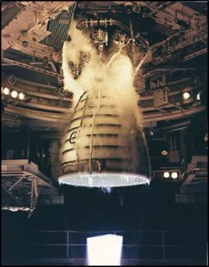
Picture1First, there is the flash and then, quickly, the wave of noise swallows you where you stand.  Unless you are there, you cannot appreciate the volume of the sound.  It is not mechanical exactly.  It is certainly not musical.  It is not a howl or a screech.  It is, rather, a rumble through your chest and a shattering roar and rattle through your head.  You think instinctively to yourself that something this primal, this terrible must be tearing the night asunder; it surely must be destructive, like a savage crack of thunder that continues on and on without yielding.  You are deafened to everything else, deprived of hearing because of all that you hear.  Yet before your eyes there is the small yet piercing brightness of the engine nozzle exit that can just be seen on what you know to be deck 5 of the stand and, to the right, there are flashes of orange flame stabbing into the billowing exhaust clouds mounting to ten stories high, tinged rusty in the fluctuating shadows.  It is like a bomb exploding continuously for eight minutes and yet the amazing thing, in incongruent fact so difficult to grasp as you are trying to absorb and appreciate the sensation is that the whole event is controlled and contained.  You cannot believe that so much raw power can be expressed by what is only a distant dot within your field of vision.

This is an experience that I wish everyone could have.  There are so many extraordinary feats of engineering all around us that we can appreciate and admire, but nothing for me has ever been as visceral as seeing an engine test, especially at night, with the nozzle open to the night air (and not buried in a diffuser).  No engine schematic or listing of characteristics or series of still pictures is an adequate substitute for the majesty of that controlled power.

Since that first test, I’ve seen any number of other engine tests including SSME (what we now call RS-25), a couple of other, smaller engines, and, of course, J-2X.  But it was not until the end of June of this year that I again had the opportunity to see a nighttime test on NASA SSC test stand A1.  This was J-2X E10002.  Below is the video, and it’s really cool, but I wish that you could have been there, standing beside me in the parking lot.  Listen carefully to the end of the recording and you’ll hear people cheering.  I was amongst the appreciative, awestruck chorus.


LEO Progress: J-2X to Test Stand A1

“Nothing behind me, everything ahead of me, as is ever so on the road.”
– Jack Kerouac, On the Road

Recently, J-2X development engine 10002 was on the road.  If you remember, E10002 went through a six-test series on test stand A2 that began in February and finished up in April.  The next planned phase of E10002 testing is on test stand A1.  In between these series, the engine was back in the assembly area of NASA Stennis Space Center Building 9101.

1038170

This respite between test series allowed for a complete series of inspections of the engine hardware.  This is vital piece of the learning process for engine development.  The basic truth is that a rocket engine is just darn tough on itself when it fires.  The reason that we test and test and test is to make sure that our design can stand up to the recurring brutal conditions.  The chance to look for the effects of that testing through detailed inspections away from the test stand is an opportunity to collect a great deal of useful information.

Also, even before the engine arrived at the assembly area, the stub nozzle extension was removed.  This was done while the engine was still installed in the test stand.  Remember, the testing on test stand A2 was performed with a passive diffuser and so we were able to use an instrumented stub nozzle extension to examine the nozzle thermal environments.  On A1, there will be no diffuser.  We’ll be firing straight into the ambient Mississippi afternoon and so we’ll not have any nozzle extension attached.  The other change made to the engine — this one made while in the assembly area — was that we swapped out the flexible inlet ducts so that we can use our specially instrumented ducts for the gimbal testing on A1.  These ducts will provide a great deal of unique data when we gimbal the engine and force the inlet ducts to twist and bend and they are designed to do.

Below is my favorite picture from the recent assembly activities for E10002 back in Building 9101.

1038171

“FOE” stands for “foreign object elimination.”  I love this picture because it is a demonstration of how dedicated and meticulous are our assembly techs and how much basic integrity they bring to their job every single day.  In the rocket engine business we tend to be fanatics about foreign objects (i.e., random debris of unknown origin) hanging around.  The reason for this is that if you spend enough time in the business, you will eventually have a story of what happens when trash gets into the engine.  The rocket in question might be an amazingly powerful beast pumping out five hundred pounds of propellant per second generating 300,000 pounds of thrust, but all it takes is one bit of junk in the wrong place to destroy the whole thing in fractions of a second.

In the picture above is a small nut that was found in the periphery of the assembly area.  Shoot, if this was my garage you’d be lucky to find a clean patch not strewn with various bits of stuff like nuts, bolts, wads of duct tape, old hunks of sandpaper, that lost pair of pliers, a “Huey Lewis and the News” cassette, or, well, who knows what.  But the rocket engine assembly area is NOT my garage (thank goodness).  When something is found like a stray nut in the picture above, that sets off an investigation.  Where did it come from?  How did it get loose?  What procedure allowed this nut to escape control?  This is serious stuff.  Yet, just think about how easy it would have been for a tech to see that stray nut, pick it up, and stick it in his pocket.  They could have avoided the whole minor investigation thing entirely.  But that’s not what they did and that is not what they do.  Because they know that if they do not show the necessary integrity and methodical approach to continue to learn and perfect our procedures, then the next stray nut could be lodged where it could do terrible damage.

Here are the techs moving E10002 out of its assembly bay and unpacking it for transport.

1038172

And a couple more pictures of the process in Building 9101.

1038173

Here’s the engine ready for the road, then being lifted up the side of the test stand, and then sitting in the porch area while sitting on the engine vertical installer.  I really enjoy the pictures of the engine trucking about sunny NASA SSC.  That picture was the inspiration for including the Jack Kerouac quote at the beginning of the article.  It’s bright and shiny and full of so much thrill and promise.

1038174

All of this should look reasonably familiar.  It is the process that we follow, more or less, whenever we take an engine out to the stand.  Getting the engine into and out of A1 is a bit easier since you don’t have to deal with moving the diffuser out of the way, but they’re really quite similar.  The slightly different flavor that we’ve got for this testing is the addition of the thrust vector control system.  In the picture below you can see where these hang.  The engine mounts up with the gimbal bearing to the stout, yellow thrust take-out structure.

1038175

The two hydraulic actuators are also attached to the thrust take-out structure but slightly outboard and at 90 degrees apart.  These actuators are what will swing the engine around as if we were steering a vehicle.  Here, below, is another, closer view of the thrust take-out structure and the actuators.

1038176

In the picture below, E10002 is mounted up to the thrust take-out structure.  The gimbal bearing is the shiny object towards which the arrow is pointing.  If you look over to the right side of the picture, you can see one of the “scissors ducts,” i.e., the flexible propellant inlet ducts.

1038177

The next picture shows one of the hydraulic actuators hooked up to the engine.  As you can see the tolerances are awfully tight.  That’s an important vehicle integration consideration.  If this was a vehicle stage rather than a test stand to which we were attaching the engine, the thrust structure and the actuators would be the responsibility of the stage manufacturer.  Making sure that the stage and the engine can work together in such close quarters takes a great deal of vigilance between the two teams.

1038178

So, you’re probably asking yourself, to what do these actuators connect on the engine?  That’s a very good question.  It certainly isn’t obvious from the assembly pictures.  The actuators connect to the forward manifold of the main combustion chamber (MCC).  Below is a computer model of the MCC with the two actuator attachment points shown.

1038179

The MCC is really the heart of the whole engine, the sturdy framework stuck right in the middle, so it makes sense that when you want to push the engine around, this is what you’d have to push.  This final picture below of the engine completely mounted into the stand.  Again, it’s amazing to think about that whole thing being able to move about and not having one component run into another component or the actuators or the stand.  It is quite the integration miracle.

1038180

Testing for E10002 on test stand A1 will commence in June.  So, if all goes well, for the next J-2X update, I’ll be able to link in a video of the engine firing and twisting about.

BTW, NASA is in the process of swapping software used for posting blog articles and comments and such.  As part of this process, they have to shut down the capability to accept input comments for a short time, specifically the first two weeks of July 2013.  Sorry about that.  But after that, it ought to be up and running as normal.

LEO Progress: RS-25 Adaptation

I love dictionaries (yes, I know, you’re shocked; shocked!).  I have several at home and at work including a two-volume abridged Oxford English Dictionary (OED) that was a wonderful gift from my mother several years ago. 


The definitions and word origin above comes from the OED on-line site.  Embedded within our language is so much condensed history and accumulated knowledge that it’s amazing.  While I have no doubt that this is true of every language, I only know my own to any significant degree.  Indeed, I’ve been babbling my own language for a long time now — forty-some years — but I can always pick up a dictionary and learn something new with just the flick of a page or two.  You really can’t say that about too many other things.

As the title for the article and the definitions above suggest, for this article we’re going to talk about “adaptation,” specifically about adaptation of the RS-25 engine.  As part of the Space Launch System Program, we are undertaking something a bit unusual for the world of rocket engines.  We are taking engines designed for one vehicle and finding a way to use them on another vehicle.  Now, this is not a completely unique circumstance.  The Soviets/Russians really were/are masters of this kind of thing.  But for us, it is not something that we do very often.  In terms of the big NASA program rocket engines, I can only think of the RL10 that was originally part of the Saturn I vehicle as an engine design that has had a long second and even third career on other vehicle systems.  The truth is that engines and vehicles are, for us, generally a matched set and the reason is that we just don’t frequently enough build that many of either.  Note that, technically speaking, we are also adapting the J-2X from a previous program, Constellation/Ares, but that’s obviously a bit different in scope and scale given where we are in the development cycle.
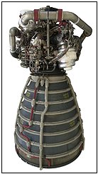
The name “RS-25” is, as I’ve mentioned in past articles, the generic name for the engine that everyone has known for years as the “SSME,” i.e., the Space Shuttle Main Engine.  There is much to talk about the RS-25.  Lots and lots of stuff.  More stuff that I could possibly fit into a single article.  Here are just some of the RS-25 topics that we’ll have to defer to future articles:

       •  History and evolution
       •  A tour of the schematic
       •  Engine control, performance, and capabilities

For this article, I want to just talk about the scope of work that will be necessary to adapt RS-25 to suit the Space Launch System Program. 


Clear Communication
The most significant thing that has to be done to the RS-25 to make suitable for the new program is that it has to be able to respond to and talk to vehicle.  Remember, the Space Shuttle was developed in the 1970s and first flown in the 1980s.  Yes, many things were updated over the years, but given the lightning-fast speed of computer evolution and development, it is not surprising that what RS-25 is carrying around a controller basically can’t communicate with the system being developed today for the SLS vehicle.  The SLS vehicle would say, “Commence purge sequence three,” and the engine would respond, “Like, hey dude, no duh, take a chill pill” and then do nothing (my lame imitation of 1980s slang as best I remember it).


But here are the neato things that we’ll be able to do: We can use almost all of the work now completed on the J-2X engine controller hardware to inform the new RS-25 controller and we can use the exact same basic software algorithms from the SSME.  Because the RS-25 has a different control scheme from the J-2X, we cannot use the exact controller unit design from J-2X, but we can use a lot of what we’ve learned over the past few years.  And, because we can directly port over the basic control algorithms, we don’t have to re-validate these vital pieces from the ground up.  We just have to validate their operation within the new controller.  That’s a huge savings.

This is work that is happening right now, as I’m typing.  Pratt & Whitney Rocketdyne, the RS-25 developer and manufacturer, is working together with Honeywell International, the electronic controller developer, on this activity.  Within the next couple of months, they will have progressed beyond the point of the critical design review for both the hardware and software. 

In the long term, it is our hope that we will evolve to the utopian plain of having one universal engine controller, a “common engine controller,” that can be easily fitted to any engine, past, present, or future.  Such a vision has in mind a standardization of methods and architecture such that we could largely minimize controller development efforts in the future to the accommodation of obsolescence issues.  The simple truth is that development work is always expensive.  It would be nice to avoid as much as that cost as possible.  With the new RS-25 controller, we’re getting pretty close to that kind of situation.

Under Pressure
Have you ever spent much time thinking about water towers?  As in, for instance, why are they towers in the first place?  As you might have guessed, this is something that I wondered about many years ago as a pre-engineering spud.  They seemed to be an awfully silly thing to build when you could just turn on the faucet and have water spurt out whenever you want.  Ah, the wonderful simplicity of childhood logic:  Things work just because they do and every day is Saturday.

The reason that you go to the trouble of sticking water way up in a tower is so that you have a reliable source of water pressure that can absorb the varying demands on the overall system.  In the background, you can have a little pump going “chug, chug, chug” twenty-four hours per day pushing water all of the way up there, but by having this large, reserve quantity always in the tower, the system can respond with sufficient pressure when, at six in the morning, everyone in town happens to turn on the shower at the same time to start their day.  The pressure comes from the elevation of tower, the height of the column of water from top to bottom.

On the Space Launch System vehicle we have something of a water tower situation except that, in this case, we’re dealing with liquid oxygen.  In the picture below, you can see roughly scaled images of the Space Shuttle and the Block 2 Space Launch System vehicle.  On both of these vehicles, the liquid oxygen tank is above the liquid hydrogen tank.  This means that for the very tall SLS vehicle, the top of oxygen tank is approximately fifty feet higher relative to the inlet to the engines (as illustrated).  This additional fifty feet of elevation translates to more pressure at the bottom just as if it were a taller water tower.  However, in this case liquid oxygen is heavier than water (meaning more pressure) and the SLS vehicle will be flying, sometimes, at accelerations much higher than a water tower sitting still in the Earth’s gravitational field.  Greater acceleration also amplifies the pressure seen by the engines at the bottom of the rocket.


“So what?” you’re saying to yourself as you read this.  After all, higher pressure is a good thing, right?  If you have more pressure at the inlet to the engine, then you don’t need as much pumping power.  So, life should be easier for the engines with this longer, taller configuration.  There are two reasons why this is not quite the case.

First, think about when the vehicle is sitting on the pad at the point of engine start.  The pumps aren’t spinning so all the pressure you’re dealing with is coming from the propellant feed system.  And now, simply, for the SLS vehicle it will be different than before.  One of the tricky things about a staged-combustion engine, in general, is that the start sequence (i.e., the sequence of opening valves, igniting combustion, getting turbopumps spun up) is touchy.  Given that the RS-25 has two separate pre-burners — and therefore three separate combustion zones — and four separate turbopumps, the RS-25 start sequence especially touchy.  You have to maintain a very careful balance of combustion mixture ratios that allow things to light robustly, but not too hot, and a careful balance of pressures throughout the system so as to keep the flow headed in the right direction and keep the slow build to full power level as smooth as possible.  We have an RS-25 start sequence that works for Space Shuttle.  Now, for the SLS vehicle, we will have to modify it to adapt to these new conditions.

The second issue to overcome with regards to the longer vehicle configuration and the liquid oxygen inlet conditions is due total range of pressures that the engines have to accommodate.  When sitting on the launch pad, you have the pressure generated by the acceleration of gravity.  During flight, as you’re burning up and expelling propellants, the vehicle is getting lighter and lighter and you’re accelerating faster and faster, you can reach the equivalent of three or four times the acceleration of gravity.  So that’s the top end pressure. 

On the low end, you have the effect of when the boosters burn out and are ejected at approximately two minutes into flight.  When this happens, the acceleration of the vehicle usually becomes less than the acceleration of gravity meaning that the propellant pressure at the bottom of the column of liquid oxygen can get pretty low.  Momentarily, the vehicle seems to hang, almost seemingly falling, despite the fact that the RS-25 engines continue to fire.  Pretty quickly, however, the process of picking up acceleration begins again.  (In the movie Apollo 13, they illustrated a similar effect with the separation of the first and second stages of Saturn V.  The astronauts are pushed back in their seats by the acceleration until, boom, first stage shutdown and separation happens and they’re effectively thrown forward.  With the Space Shuttle and the SLS vehicle, however, the return to acceleration is not as abrupt as it was on Saturn V where they show the astronauts slammed back into their seats with the lighting of the second stage.)  The point is that the RS-25 has to accommodate a very wide range of inlet pressures while maintaining a set thrust level and engine mixture ratio.  While this has always been the case for the SSME/RS-25, the longer SLS vehicle configuration simply exacerbates the situation.

You’ll note that I’ve not talked about the liquid hydrogen here.  That’s because, as I’ve mentioned in the past, liquid hydrogen is very, very light.  Think of fat-free, artificial whipped cream.  Yes, the top of the hydrogen tank is much higher, but due to the lightness of the liquid, it doesn’t make much difference at the engine inlet even when the vehicle is accelerating at several times the acceleration of gravity.

Some Like it…Insulated
Look again at the pictorial comparison of the Space Shuttle and the Space Launch System vehicles shown above.  Do you see where the SSME/RS-25 engines are relative to the big boosters on the sides of the vehicles?  On the Space Shuttle, the engines were on the Orbiter and they were forward of the booster nozzles.  On the SLS vehicle, there is no Orbiter so the engines are right on the bottom of the tanks and their exit planes line up with the booster nozzle exit planes.  In short, the engines are now closer to those great big, loud, powerful, and HOT boosters.  We are in the process now of determining whether this poses any thermal environments issues for the RS-25.  Thus far, based upon analyses to date, there do not appear to be any thermal issues that cannot be obviated through the judicious use of insulation.
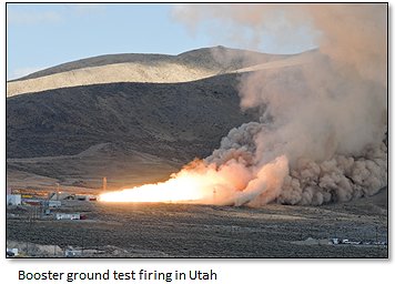
Other environments also have to be checked such as the dynamic loads transmitted to the engine through the vehicle or the acoustic loads or whatever else is different for this vehicle.  The point is not that all of these environments are necessarily worse than what they were on the Space Shuttle.  It is only that they all need to be checked to make sure that our previous certification of the engine is still valid for all of these considerations.

The Tropic of Exploration
So those are the three most obvious and primary pieces of the RS-25 adaptation puzzle: a new engine controller, dealing with different propellant inlet conditions, and understanding the new vehicle and mission environments.  Each of these pieces carries with it analysis and testing and the appropriate documentation so there is plenty of work scope to accomplish.  We are extremely lucky to be starting with an engine of such extraordinary pedigree, performance, and flexibility. 

Henry Miller once said, “Whatever there be of progress in life comes not through adaptation but through daring.”  It is our intent to prove Mr. Miller wrong in this case.  We will make progress by using the adaptation of RS-25 to enable the daring of our exploration mission.
J-2X Progress: Current Status, The End of 2012

Once upon a time, not that long ago, people used to communicate by what were known as “letters.”  These were written documents.  Yes, actual hardcopy, paper items. And they were often transcribed by hand or, sometimes, generated on what was known as a “typewriter,” which was basically a manual, analog printer with no I/O port beyond direct keypad entry.  These “letters” were sent to their intended recipients using a small denomination currency with an adhesive backing that is recognized for exchange by only one quasi-governmental agency. 


I know that some of you may have doubts that people communicated with each other in primitive ways prior to email and text messages, but witness the cultural clues from the 1961 song illustrated above. 

It was always believed that the toughest letter to receive was the dreaded “Dear John” letter (as in, “Dear John, I’ve fallen in love with someone else…”).   However, I think t’at the hardest letter to write is the “it’s been awhile” letter.  This one starts, “Well, it’s been awhile since I’ve written.  Sorry.”  This blog article is just like one of those letters.  It’s been awhile since I’ve written one of these articles and I’m sorry about that.  I could give you a big long list of all the really, really serious stuff that I’ve been doing instead, but that’s just a bunch of feeble excuses so I’ll keep them to myself.  Instead, I’ll just get down to business and give you a status report on the J-2X development effort.

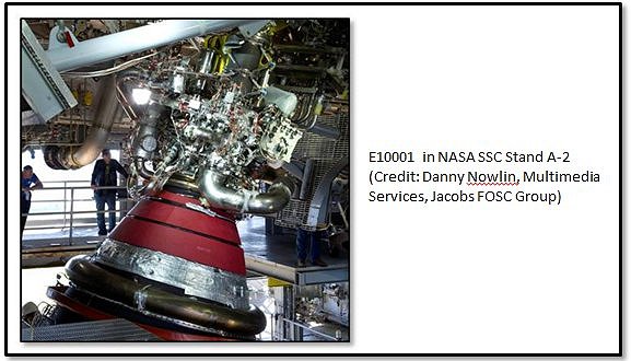
Engine #1 (E10001) Testing is Complete!
Over fourteen months and across the span of twenty-one tests, more than 2,700 seconds of engine run time was accumulated and recorded, including nearly 1,700 seconds of hot fire with an instrumented nozzle extension.  With this engine we achieved stable 100% power level operation by the fourth test and full mission duration by the eighth test.  While we don’t have any official statistics on the issue, most folks around here believe that we accomplished those milestones faster than has ever been done on a newly developed engine.  We learned how to calibrate the engine and the sensitivities that the engine has to different calibration settings, i.e., orifice sizes and valve positions.  We were able to estimate performance parameters for the full-configuration of the engine at vacuum conditions and the calculations suggest strongly that all requirements are met by this design and met with substantial margin.  This is significant considering that we’ve long considered our performance goals to be pretty aggressive.  Well, our little-engine-that-could showed us that it did just fine with those goals, thank you very much.

One of the truly unique and successful aspects of the E10001 testing was the testing of a nozzle extension.  This component is a key feature that allows J-2X performance to far exceed that of the J-2 engine from the Apollo Program era.  While it is true that we cannot test the full-length nozzle extension without a test stand that actively simulates altitude conditions, we did test a highly instrumented “stub” version that allowed us to characterize the thermal environments to which the nozzle is exposed during engine hot fire and it demonstrated the effectiveness and durability of the emissivity coating that was used.  This stub-nozzle configuration is actually the current baseline for the in-development Space Launch System vehicle upper stage.

Another key success for E10001 was the demonstration of both primary and secondary power levels with starts and shutdowns from each power level and with smooth in-run transitions back and forth between them.  That smoothness was thanks, in part, to demonstrating our understanding of the control of the engine.  From the very first test it was clear that we understood pretty well how to control the engine in terms of proper control orifices for the various operating conditions.  What we did not entirely understand — in other words the fine-tuning details — we successfully learned via trial-and-error throughout the E10001 test series.  All of this learning has been fed back into further anchoring our analytical tools and models so that we can move forward with J-2X development with a great deal of confidence.

Okay, so that’s a brief description of just some of the good stuff.  We had lots and lots of good stuff with the E10001 testing, far more than just that I’ve discussed here (see previous blog articles).  The somewhat unfortunate part was the way in which the E10001 test series came to an end.  On test A2J021, we had a disconnection between the intent for test and the detailed planning that led to the actual hardware configuration we ran for the test.  That disconnection led to an ill-fated situation.  Let me explain…

The J-2X gas generator has ports into which solid propellant igniters are installed.  These igniters are like really high-powered Estes® rocket motors that light off when supplied with a high-energy electrical pulse.  The flame from the igniter lights the fire of the hydrogen-oxygen mixture during the engine start sequence.  It’s essentially the kindling for the fire of mainstage operation.  The igniters perform this function at a very specific time during this sequence.  If you try to light the fire too early, then you may not have enough propellant available in a combustible mixture so you get a sputtering fire.  If you try to light too late, then you may have too much propellant built up such that rather than getting a good fire, you get an explosion instead.  But here’s a key fact: You have to plug them in or they don’t work.

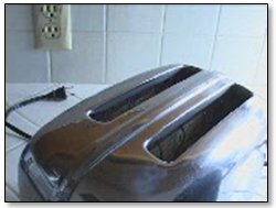
Have you ever stuck bread in the toaster, pushed down the plunger, gone off to make the coffee, and come back only to find that your darn toaster is broken?  You curse a little because you’re already late for work and this is the last darn thing you need.  You would think that somebody somewhere could make a toaster that lasts more than six months or a year or whatever.  For goodness sake!  We put a man on the moon and yet we can’t … oh, wait … um … ooops, it’s not plugged in.  My bad.

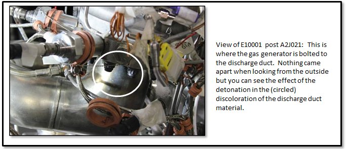
In a nutshell, that’s what happened on test A2J021.  The electronic ignition system sent the necessary pulse, but because of the uniqueness of our testing configuration as opposed to our flight configuration the wires carrying the pulse weren’t hooked up to the little solid propellant igniters in the gas generator.  In the picture below you can see the external indication that something was not entirely good immediately after the test.  The internal damage was more extensive to both the gas generator and the fuel turbopump turbine.

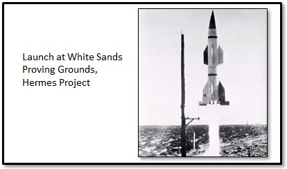
Many years ago, I met an elderly engineer who was still on the job well into his 80’s because he loved his work.  His entire career had been dedicated to testing.  He’d actually been there, out in the desert, in the 1940’s testing our very earliest rockets as part of the Hermes Project.  One day, they had a mini disaster on the launch pad.  He told me that the rocket basically just blew up where it sat.  Boom and then a mess.  And, it was his job to assemble the test report.  Being a conscientious, ambitious, young engineer, he recorded the facts and offered a narrative abstract and extensive, annotated introduction that categorized the test as, well, a failure.  Not long after submitting his report, one of the senior German engineers in the camp came into his office, put the test report down on the desk, and said that the tone of the report was entirely wrong.  He said, “Every test report should begin with: ‘This test was a success because…'”  The purpose of testing is to gather data and learn.  If you learn something, then your test was, by definition, a success on some level.  I’ve tried very hard to remember this very important bit of wisdom.

So, A2J021 was a success because we learned that we had some deficiencies in our pre-test checkout procedures.  It was a success because it was an extraordinary stress test on the gas generator system.  No, it didn’t recover and function properly, but neither did the engine come apart.  While that might seem like a minor detail, when you’re hundred miles from the surface of the earth, you would much rather have a situation where an abort is possible than a failure that could result in collateral vehicle damage and make safe abort impossible.  We have a stout design.  Good.  Also, this test failure was due to a unique ground test configuration.  In flight, it’s not really plausible just because we would never fly in this configuration.

So, E10001 completed its test program with a bang.  Kinda, sorta literally.  But it was nearly the end of its design life anyway, so we didn’t lose too many test opportunities, and, as I said, even with test A2J021 the way it happened we learned a great deal.  Overall, the E10001 test series was an outrageous success.  Rocketdyne, the J-2X contractor, ought to be darn proud and so should the outstanding assembly and test crews at the NASA Stennis Space Center and our data analysts here at the NASA Marshall Space Flight Center.  Bravo guys!  Go J-2X!

Power-Pack Assembly 2 (PPA-2) Testing is Complete!
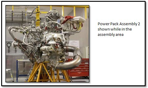
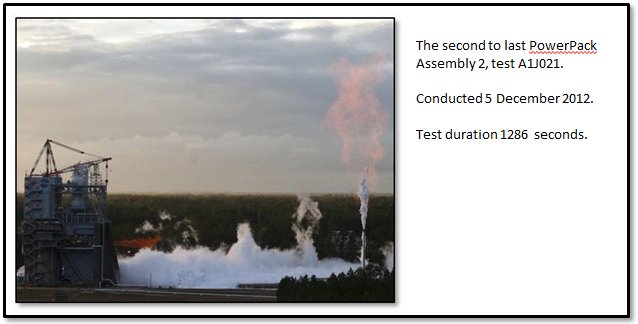
Over ten months and across the span of thirteen tests, nearly 6,200 seconds of engine run time was accumulated and recorded on the J-2X Power Pack Assembly 2.  That’s over 100 minutes of hot fire.  Three of the tests were over 20 minutes long (plus one that clocked in at 19 minutes) and these represent the longest tests ever conducted at the NASA Stennis Space Center A-complex.  But more than just length, it was the extraordinary complexity of the test profiles that truly sets the PPA-2 testing apart.

Because PPA-2 was not a full engine with the constraints imposed by the need to feed a stable main combustion chamber, and because we used electro-mechanical actuators on the engine-side valves and hydraulic actuators on the facility side valves, we could push the PPA-2 turbomachinery across broad ranges of operating conditions.  These ranges represented extremes in boundary conditions and extremes in engine conditions and performance.  On several occasions we intentionally searched out conditions that would result in a test cut just so that we could better understand our margins.  As the saying goes: It’s only when you go too far do you truly learn just how far you can go.  We successfully (and safely) applied that adage several times.  In short, we gathered enough information to keep the turbomachinery and rotordynamics folks blissfully buried in data for months and months to come. 

On an interesting and instructive side note, the PPA-2 testing also showed us that we needed to redesign a seal internal to the hydrogen turbopump.  In the oxygen turbopump, you have an actively purged seal between the turbine side and the pump side.  After all, during operation you have hydrogen-rich hot gas pushing through the turbine side and liquid oxygen going through the pump side.  You obviously don’t want them to mix or the result could be catastrophic.  That’s why we have a purged seal.  But for the hydrogen turbopump you don’t have such an issue.  During operation, at worst should the two sides mix you could get some leakage of hydrogen from the pump side into the turbine side that is already hydrogen rich.  In order to maintain machine efficiency, you don’t want too much leakage, but a little is not catastrophic (and can be used constructively to cool the bearings).  What could be dangerous at the vehicle level, however, is if you have too much hydrogen floating around prior to liftoff.  This is especially true for an upper-stage engine like J-2X that’s typically sitting within an enclosed space until stage separation during the mission.  You could have the engine sitting on the pad for hours chilling down and filling the cryogenic systems and you don’t want gobs and gobs of hydrogen leaking through the turbopump since any leakage ends up within the closed vehicle compartment housing the engine.  That’s just asking for an explosion and a bad day.

To avoid this, within the J-2X hydrogen turbopump we have what is called a lift-off seal.  And, as the name applies, it’s a seal that actively lifts off when we’re ready to run the engine.  When the engine is just sitting there chilling down, not running, with liquid hydrogen filling the pump end of the hydrogen turbopump, the seal is, well, sealed.  Then, when we’re ready to go, it unseals and allows the turbopump to operate nominally.

During the PPA-2 test series we found that we formed a small material failure within the actuation pieces for our lift-off seal.  Then, upon analysis of the test data and a reassessment of the design, we figured out what was most likely the cause and Rocketdyne proposed a redesign to mitigate the issue.  Again, going back to that important piece of wisdom: This testing was a success because, in part, we learned that we needed a slight redesign of the lift-off seal.  That’s the whole purpose of development testing!  Everything always looks great when it’s just in blueprints.  It’s not until you hit the test stand do you truly learn what’s good and what need to be reconsidered.  In the end, this sort of rigor and perseverance is what gives you a final product that you feel good about putting in a vehicle carrying humans in space.  And that, truly, is what it’s all about.

As with E10001, the PPA-2 test series was simply an outrageous success.  Rocketdyne should be proud and so should the outstanding assembly and test crews at the NASA Stennis Space Center and the data analysts at the NASA Marshall Space Flight Center.  Bravo guys!  Go J-2X!

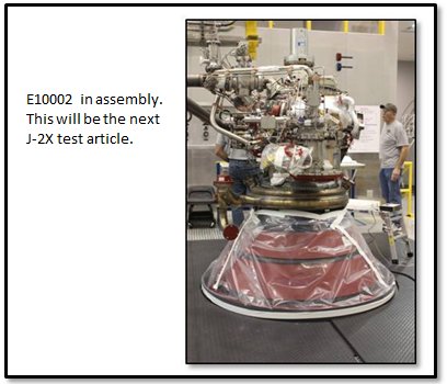
Engine #2 (E10002) Assembly is Underway
Our next star on the horizon is J-2X development Engine 10002.  It is being assembled right now, as I’m typing this article.  It is slated for assembly completion in January 2013 and it will be making lots of noise and very hot steam in the test stand soon after that.  While our current plans are to first test E10002 in test stand A2, we will later be moving it to test stand A1.  This, then, will be the first engine then to see both test stands.  The more important reason for the A1 testing, however, is because that will give us the opportunity to hook up some big hydraulic actuators and gimbal the engine, i.e., make it rock and tilt as though it were being used to steer a vehicle.  Now that will be some exciting video to post to the blog!  I can’t wait.

 
Happy New Year!
So, this has been my “it’s been awhile” letter.  Hopefully this will bring everyone up to speed with where we stand with J-2X development.  In my next article, I will share with you some of what’s been keeping me from my J-2X article writing over the last several months.  And, hopefully, it won’t be several months in the making.  So, farewell for now and Happy New Year!  On to 2013 and another great year full of J-2X successes.  Go J-2X!