I enjoy movies. I don’t get to watch much television due to other endeavors that consume much of my time, but if I do it’ll almost always be one of four things on the screen: some news program, a sporting event, a history program, or a movie. And I like lots of different kinds of movies. Some of my favorites include: The Hustler, Singing in the Rain, Rocky, Schindler’s List, Barfly, Hannah and Her Sisters, Fargo, The Apartment, The Godfather, Leaving Las Vegas, The Deer Hunter, Hoosiers, Nobody’s Fool (the Paul Newman one). I don’t believe that one could decipher a pattern from that list other than the fact they all follow the classic narrative structure:
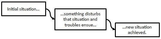
Think of the classic “stranger comes to town” story. (1) It’s a quiet little town and all is peaceful. (2) Then a stranger comes to town and stirs up all kinds of trouble. (3a) In the end, the stranger marries and settles down with the prom queen and everyone learns to live with one another. Or, (3b) in the end, the stranger ends up mysteriously dead and lying in the gutter along the road leading out of town and they secretly bury him promising never to mention it to anyone from out of town. Or, (3c) in the end, the stranger ends up mayor of the town by exposing and driving out the secretly corrupt sheriff. Obviously, the possibilities are endless and that’s why there are thousands and thousands of stories to be told. But the root of all of this is the middle block, “…something disturbs that situation and troubles ensue…” Nobody ever tells an interesting story where nothing happens. And with no “troubles” of some sort, nobody cares about the resolution.
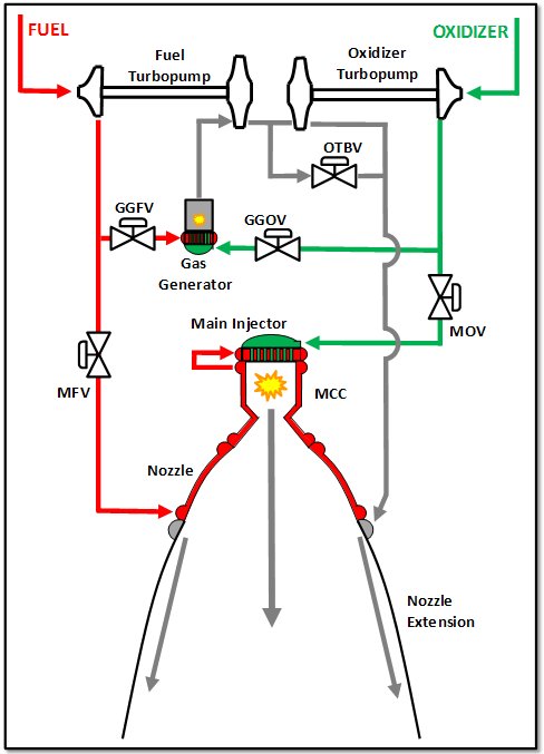
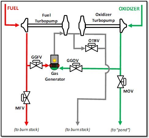
So, that brings me to rocket engine testing and the fact that it is always interesting. This article is intended to bring you up to date on the status of our J-2X test campaign at the NASA Stennis Space Center in southern Mississippi. Remember, we last left our heroes on test stand A1 with PowerPack-2…
Test A1J015, J-2X PowerPack-2: It ran 340 seconds of a planned 655 seconds duration. The test profile called for simulated primary mode and secondary mode (i.e., throttled) operation. Also, throughout the test, turbomachinery speed sweeps were planned meaning that we systematically varied turbine power, increasing and decreasing, to force the pumps through a broad range of conditions. It was during one of these sweeps that the fuel turbopump crossed a minimum speed redline and the test was cut short. Before the test, we knew that it would be close and the analytical prediction was just enough off from reality to cause the early cut. Nevertheless, most of the primary objectives were achieved and the test was a success.
One of the things that we often talk about when discussing an engine test is the “test profile” or sometimes the “thrust profile.” The test/thrust profile is the plan for what you’re going to do during the test. When we say that we had a planned duration of 655 seconds, that value comes from the test profile that is agreed upon prior to the test. Usually a test/thrust profile is a single page showing engine power levels and propellant inlet conditions, but for these complex PPA-2 tests, the test profile can be expanded to include such things as these turbomachinery speed sweeps. To give you an idea of what an engine test/thrust profile looks like, here is one for a Space Shuttle Main Engine (SSME) test performed back in 2001. It contains a wealth of knowledge about the test to be run.

Test A1J016, J-2X PowerPack-2: It ran 32 seconds of a planned 1,130 seconds duration. In this case, unlike the previous test, because we cut so early we can’t really say that it was mostly a success. However, every time that you chill an engine, successfully get it started, and shut it down safely, you have accomplished something significant and you are always collecting data and learning. The early cut in this case had nothing to do with the PowerPack-2 performance. Rather, it was a facility issue, a hydrogen fire due to a leak. As I’ve said before, the PowerPack-2 is an oddball test article in that it is half engine and half facility. That makes the interfaces technically difficult in some cases due to thermal and structural loads. The leak and fire in this case was on the facility side near one of these difficult interfaces.
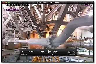
Below is a picture captured off a video taken during the test and behind the structure and the piping you can see the bright orange flame that resulted in the early cut. This issue of hydrogen leaks and fires has been somewhat recurring so a team of NASA and contractor folks stepped forward to work towards a resolution of the issue.
Test A1J017, J-2X PowerPack-2: It ran the full, planned 1,150 seconds duration. That’s over 19 minutes of continuous rocket engine operation and that’s pretty amazing. It was the longest, most complex engine test ever conducted across the long history of the NASA Stennis Space Center A Complex. We did some wacky stuff on test stand A1 during the XRS-2200 (linear aerospike engine) development effort and there were a couple of longer SSME tests in the B Complex twenty-some years ago, but test A1J017 stands out for the combination of complexity and duration. The test profile contained over a dozen unique, steady state “set points,” i.e., prearranged combinations of engine operational conditions and facility boundary conditions. The objectives of this test included speed sweeps for the oxidizer turbopump and an examination of cavitation performance for both the oxidizer pump and the fuel pump. Pulling off this test was a dazzling success with many people deserving credit.
So, trouble ensues (hydrogen fire on test #16) and the combined team of NASA Stennis, NASA Marshall, test operations and support contractors, and Rocketdyne worked through to a resolution of the issue and a new situation of unprecedented success has been achieved. It’s easy to write a blog like this when reality lines up so conveniently in the narrative form.
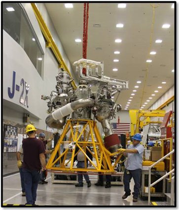
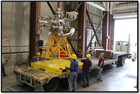
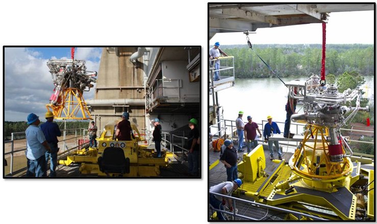
But back at the ranch, our heroes find J-2X development engine E10001 on test stand A2…
To refresh your memory, we’d last tested E10001 on stand A2 back in December of last year. Back then, we were testing the engine without a nozzle extension and not using the passive diffuser system on the stand. This year, we were going to get back to testing E10001 but now with a nozzle extension so that necessitated use of the passive diffuser. The Stennis folks installed a clamshell and seal apparatus that connects the engine to the diffuser thereby allowing the diffuser to “suck down” to pressures lower than sea level ambient. In my crude sketch below, I try to show you how this fits together.
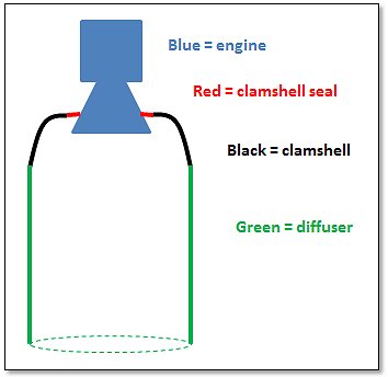
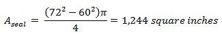
A key piece in this arrangement is the clamshell seal. Whereas the engine is obviously metal and the clamshell and diffuser and big pieces of structural metal, the clamshell seal is a fibrous/rubber-ish piece that has to provide the seal that allows the whole thing to work together and simulate altitude operation when the engine is running. It has to be strong yet compliant so as to accommodate movements of the nozzle during hot fire. To give you an idea of how strong it needs to be, let’s calculate the force imposed on the seal during operation. Ambient sea level pressure is 14.7 psia (pounds per square inch, absolute). Let’s say that in the diffuser, during operation, it will be about 10 psi lower than sea level ambient. In reality, the pressure will be slightly lower than that, but 10 is a nice round number to work with. Let’s further say that the diameter of the nozzle at which the seal is attached is about five feet (or, 60 inches). That’s pretty close to reality, give or take a bit. And, let’s say that the seal itself is about six inches in width. So, the total area of the seal is:
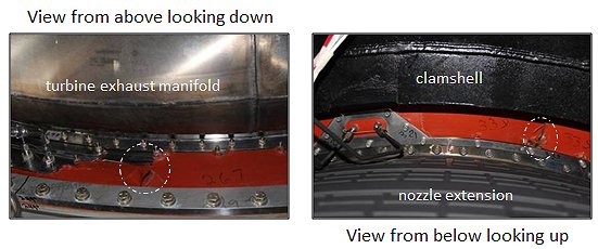
Test A2J011, J-2X E10001: It ran 3 seconds of a planned 7 seconds duration. The early cut was due to a facility redline violation; specifically, the measured pressure within the clamshell did not drop down the way that it was supposed to. Post-test inspections quickly revealed why this redline violation occurred. The clamshell seal was torn up. If the seal doesn’t seal, then the pressure differential is not maintained and so, appropriately, we tripped a redline.
An informal team was assembled of NASA, contractor, and Rocketdyne folks and the design deficiency was quickly identified. New parts were designed and fabricated and, in a matter of just a couple of weeks, we were once again ready for test.
Test A2J012, J-2X E10001: It ran the full, planned 7 seconds duration. The objectives for this test were to demonstrate that the clamshell, seal, and diffuser arrangement was properly working and to perform a bomb test in the main chamber. The testing arrangement worked perfectly and the bomb test did not reveal any combustion stability issues.
Test A2J013, J-2X E10001: It ran the full, planned 40 seconds duration. This was yet another bomb test and again there was no combustion stability issue uncovered. The neato thing on this test was that while the engine started to primary mode operation (i.e., 100% throttle), it switched to secondary mode operation (i.e., throttled) mid-test. This was the first operation of the complete J-2X engine (as opposed to just the powerpack portions) in secondary mode.
Test A2J014, J-2X E10001: It ran the full, planned 260 seconds duration. This test represented several more “firsts” for J-2X. This was the first time that the J-2X was started directly to secondary mode. It was the first time that the J-2X switched, in run, from secondary mode to primary mode. This was the first J-2X test with a stub nozzle extension that offered the opportunity to perform an in-run calibration of the facility flow meters and, in so doing, provide for a good estimation of engine performance. It turns out that E10001 is, to our best understanding, exceeding expectations in terms of required performance.
Again, the old narrative structure holds: New guy comes to town (the stub nozzle extension). The situation changes (new test stand configuration to accommodate the stub). Troubles ensue (the clamshell seal gets torn up). Resolution is found (new design for clamshell seal attachments). And a new situation is achieved (we’re knocking off successful test after successful test).
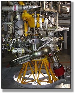
But, there is a twist (literally) to our denouement. I’ll explain this twist by starting with a picture:
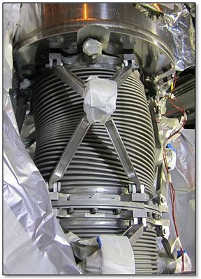
Can you see it? This is a picture of the fuel inlet duct. Remember, this duct has an inner and an outer shell (or bellows as we call them) so that in between there will be vacuum to keep the hydrogen cold, like a Thermos® bottle. Between tests, one of the customary inspection techniques used to ensure that you’re good to go for the next test is to do a series of helium leak checks. You systematically pressurize different portions of the engine and make sure that everything is still sealed up tight. Well, when they pressurized this portion of E10001, they got what we’re calling “squirm.” If you look closely at the duct you’ll see that on the left-hand side the convolutions are bunched together and on the right-hand side they’re spread apart. This indicated that there was leak in the inner bellows of the duct so that the cavity between the two bellows was pressurizing with the leak-check helium. The squirm effect was due to the outer shell was deforming — squirming — due to that pressurization of the vacuum cavity.
Now, there are several important things to note about this. First, this particular duct is a heritage piece of hardware. It was not made for E10001. It was made during the Apollo era for J-2 and J-2S, forty years ago. It had seen its fair share of hot-fire history long before it reached E10001. Second, the new ducts being built for J-2X have a design modification that ought to mitigate this kind of failure. Third, we can see in the test data, with perfect hindsight, exactly when the leak occurred in test A2J014 and the engine ran for some time with the leak and nothing catastrophic happened. Thus, while nobody is happy when something breaks, in this case there’s no need for overreaction.
Getting back to the narrative structure and this little twist at the end, I kind of think of this like a teaser — a cliff-hanger — that leads to a sequel. Will our intrepid heroes dig their way out of this situation? Will the test program recover and move ahead to new successes and glory? Or will the monster creep up from the dark, dank Pearl River swamps and terrorize the test crew…?

…oops, wrong movie.
[Hint: We’ll be fine. Already moving out at full speed. In the immortal words of Journey (i.e., Jonathan Cain, Steve Perry, and Neal Schon) “Oh the movie never ends. It goes on and on and on and on…”]