The following picture is a test. Find me amidst the mess…
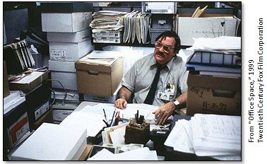
That’s right. I’m the handsome chap with the snazzy specs. See, I’m just oozing with exactly the vitality that you’d expect from your typical government-trained civil servant! Well, okay, so maybe I’m not exactly Milton Waddams. All personal resemblance and charm aside, I don’t actually have quite that much paper clutter in my office. No. Instead, I just have electronic clutter. Indeed, if someone spent the time to actually print out all the stuff on my computer here at work, then we wouldn’t need a rocket to get beyond the moon. We could just build a staircase from the resulting gargantuan pile of paper.
Why is this the case? It could be that I’m just a data hoarder. Some people hoard clothes (that’s not me). Some people hoard automobiles (that’s not me). Some people hoard books (okay, that is me). And some people hoard data. All data. All of the way back to class notes from Aerodynamics I (AERSP 311, junior year, professor Bill Holl — great teacher, great guy). Yes, okay, so maybe I’m a little guilty of all that. In my defense, however, I will simply say that there’s a lot that goes into making rocket engines and much of it is quite removed from the exciting cutting-metal stuff or the making-smoke-and-fire stuff. And I get to stick my nose into much of it. For this article, I am going to reveal super-duper, deep-and-dark secrets that they won’t even teach you in college. I am going to tell you a little about …
…wait for it…

…project management. Yes, it’s true: I am going to invite you into our little piece of office space and I will do so to tell you about how the office has recently evolved. Also, towards the end as a reward, I’ll give you an update of J-2X testing progress to date.
So, let me introduce you to LEO —

No, none of those LEOs. Instead, let me introduce you to the Space Launch System (SLS) Program Liquid Engines Office (LEO). The LEO is responsible for development and delivery of the liquid rocket engines for the core stage and upper stage of the SLS vehicle. For more information about the SLS Program in general, I highly recommend the following site: https://www.nasa.gov/exploration/systems/sls/
(Oh, and I want to say something briefly about the term “liquid engines.” Probably every single person who would bother to read a blog about engines or rockets or space travel in general knows that this is just a shorthand term. No, we are not talking about engines made of liquid — although that would be really cool. “Liquid engines” is a quick and easy way to denote “liquid-propellant rocket engines.” In case I’ve disappointed anyone, I’m sorry. If ever we are able to make an engine out of liquid, I promise to be the first to report it. Probably the most far-out thing that I once heard was the suggestion to make a hybrid rocket motor using solid hydrogen and liquid oxygen. I cannot even imagine what the infrastructure would be to make the use of solid hydrogen plausible, but you never know…)
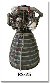
 For the SLS vehicle, the upper-stage engine is the rocket engine so near and dear to our hearts after several years of design and development and fabrication and assembly and test: J-2X. The core-stage engine is the RS-25. No, the RS-25 is not a brand new engine. Rather, it is the generic name for that workhorse of the last thirty years, the Space Shuttle Main Engine (SSME).
At the end of the Space Shuttle Program, there were fourteen SSMEs that had flown in space on the Shuttle and that still had usable life remaining. I’m not sure that everyone knows this, but rocket engines have limited useful lives. I guess that most things do, but with rocket engines it’s often pretty short. Think of them like cherry blossoms (popular motif in Japanese tattoos): amazingly beautiful and quickly gone too soon. The stresses within an operating rocket engine are tremendous. For example, the J-2X has an official, useful life of only four starts and less than 2,000 seconds of operational run time after the engine has been delivered for use as part of the vehicle. No, the engine doesn’t crumble into dust after that, but based upon our certification strategy and on our analysis of margins, that is the official life for our human-rated launch system. After that point, depending on the proposed usage and risk considerations, and based on the likely reassessment of our margins with the proverbial “sharper pencil,” we can and do routinely talk ourselves into longer active lives for engine hardware. On the test stand, we can test the J-2X upwards of 30 times and for lots of run time, but that is a lower risk situation. Nobody is riding the test stand into space.
 Thus, when you come to the end of a program and you have fourteen engines with remaining, usable life, then you’ve got one heck of a residual resource. In addition, there was one SSME assembled and ready to go, but it never made it to the test stand or the vehicle. So it’s brand new. And, on top of that, there were enough leftover pieces and parts lying around of flight-quality hardware to cobble together yet another engine. And, there’s more! (Yes, I feel like the late-night infomercial guy, “and if you call in the next 10 minutes you will get this special gift!”) There are also two development SSMEs. These are not new enough to fly, but they are useful for ground testing and issues resolution. That means that there are a total of sixteen RS-25 flight engines and two RS-25 development engines available to support the SLS Program.
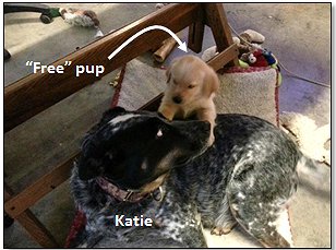
However, before your excitement bubbles over, you have to understand that when you see a sign for “free puppies,” you probably shouldn’t take that whole notion of “free” too literally. As in, well, not at all. Yes, we still have an extraordinary asset in the residual RS-25 engines. No question. But, we have work to do to integrate them into the SLS Program. In a future article, I will discuss the multiple facets of this work. By the way, I cannot claim to be immune from the “free puppies” thing myself. Meet Ruugie –
The Liquid Engines Office (LEO) was formed to manage both the J-2X and the RS-25. This office will also manage other liquid rocket engines used to support the SLS Program as it matures. It was decided from a project management perspective that it would be best to have one office manage both engines. In this way, we can be more efficient by leveraging the expertise across various disciplines and components. For example, do we really need two turbomachinery subsystem managers? No, Gary Genge is our turbomachinery subsystem manager and in that position he can understand and evaluate the relative programmatic and technical risk across all of the various turbomachinery pieces under his purview. If in some utopian future our office responsibilities expands to three or four or eight different engine development or production efforts, we would, in theory, maintain the same structure but provide Gary with the support necessary to effectively manage turbomachinery across so many activities.
So, for LEO we have subsystem managers for Engine Systems (effectively systems engineering and integration), Engine Assembly and Test (also includes asset management, logistics, and operations), Engine System Integration and Hardware, Valves and Actuators, Engine Control Avionics, Turbomachinery, and Combustion Devices. LEO is supported by a Chief Engineer, a Chief Safety and Mission Assurance (S&MA) Officer, Program Planning and Control (i.e., the business office), and Procurement. Plus, of course, we have support from the engineering and S&MA organizations across the many technical disciplines. The structure is really quite similar to how we’ve been managing J-2X for these past several years. We’ve just expanded our responsibilities.
So, that’s LEO and I’ll be talking more about RS-25 and SLS in the future.
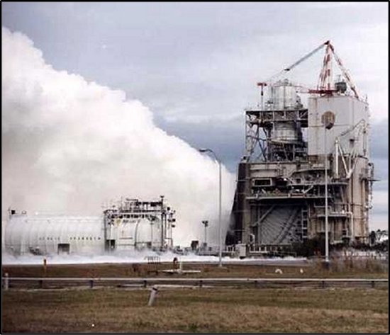
Now, while I’ve been off doing my little part to get the foundation of LEO solid, including refreshing and getting into place our prime contracts for both J-2X and RS-25, how has J-2X been doing? Well, in short, J-2X has been just cruising along. E10002 has gone through six tests on NASA Stennis Space Center (SSC) test stand A-2. Below are a series of images showing what an E10002 start looks like if you stood in view of the flame bucket (which I would very strongly advise against, by the way):
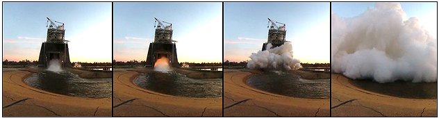
First, all you see is the facility water being pumped into the flame bucket. Then you can see the ignition and everything glows orange. Then the whole flame bucket is filled with exhaust. And, finally, the exhaust coming barrelling down the spillway and eventually engulfs the camera. The final step is not shown since there’s nothing to see but solid whitish grayness.
Here are the stats on the six tests:
• Test: A2J022 2/15/2013 35 seconds duration
• Test: A2J023 2/27/2013 550 seconds duration
• Test: A2J024 3/07/2013 560 seconds duration
• Test: A2J025 3/19/2013 425 seconds duration
• Test: A2J026 4/04/2013 570 seconds duration
• Test: A2J027 4/17/2013 16 seconds duration
So the total accumulated time is 2,156 seconds. Tests #22, #25, and #27 all experienced early cuts, but all three were instigated by different flavors of instrumentation or monitoring system issues or oddities. The engine is fine and running well. Some of the key objectives included gathering additional data about the nozzle extension cooling characteristics, additional samples of the turbomachinery design, and main chamber combustion stability trials. Something else that we did for this test series is that we tested a very special fuel turbopump port cover. Here’s a picture of it:
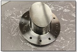
Now, port covers are not something about which one usually says anything at all. What makes this one special is that it was made by using a process known as Selective Laser Melting (SLM). That is a fabrication method that is somewhat analogous to “3-D printing.” A long time ago, I wrote a blog article about a gas generator discharge duct that we made for component-level testing using this technique. This, however, is an engine test and this small, seemingly innocuous, piece of engine hardware may be the humble harbinger of a revolution in rocket engine fabrication. The fact that we systematically stepped through the process of validating this port cover as a piece of hardware for an engine hot fire demonstration paves the way for pursuing other parts in the future, more complex parts, and, hopefully one day, regular production parts as part of a human-rated launch architecture.
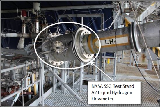
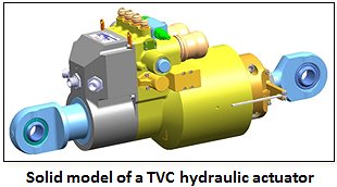
E10002 was removed from NASA SSC test stand A-2 on April 30th. It is currently being retrofitted with instrumented inlet ducts and other hardware in preparation for the next phase of testing that will occur on NASA SSC test stand A-1. As you’ll remember, in the past A-1 was used for the PowerPack Assembly testing. Well, the talented and productive folks at NASA SSC remodeled the stand back to the configuration for engine testing. The current plan is to install E10002 into A-1 by mid-May and to perform a series of five to seven tests through probably August. The reason for using A-1 for the next series is because that stand does not have a diffuser. That means that we can gimbal the engine, i.e., twist it around as if we were providing steering for a vehicle. The thrust vector control (TVC) system composed of the hydraulic push-pull actuators that will be performing the gimballing is a component belonging to the stages element of the vehicle. This testing will be providing those folks with data to inform their system design for the SLS Program. See, it’s all win-win when we play nicely together.
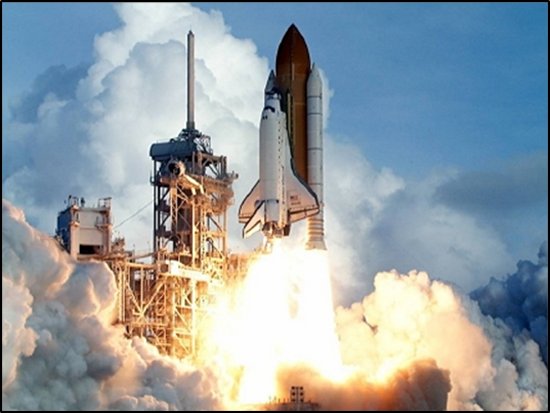
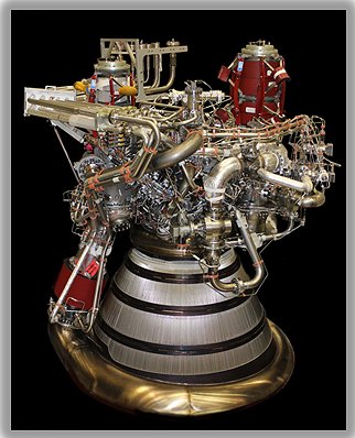
And, finally, right on the heels of E10002, the assembly of E10003 will commence in June with scheduled installation into NASA SSC A-2 in September. That’s my report for where things stand. To finish up, I’ll leave you with a purely gratuitous glamor shot of the J-2X. Isn’t she pretty?

 It was late in the evening and a little chilly. Though we’d arrived at the control center before dusk, test preparations had dragged on so that now darkness had enveloped the center. The test stand stood out against the blackened sky like a battleship docked in the distance. Brian, my team lead at the time with whom I’d driven down from Huntsville, and I were standing outside in the control room in the parking lot. The radiation from the hydrogen flair stack off to our left warmed one side of our face as the breeze cooled the opposite cheek. The wailing of the final warning sirens drifted off and all that could be heard was the burning torch of the flair stack and, in the distance, the low surging and gushing of water being pumped into the flame bucket. We were a just a couple of hundred yards from the stand.
 First, there is the flash and then, quickly, the wave of noise swallows you where you stand. Unless you are there, you cannot appreciate the volume of the sound. It is not mechanical exactly. It is certainly not musical. It is not a howl or a screech. It is, rather, a rumble through your chest and a shattering roar and rattle through your head. You think instinctively to yourself that something this primal, this terrible must be tearing the night asunder; it surely must be destructive, like a savage crack of thunder that continues on and on without yielding. You are deafened to everything else, deprived of hearing because of all that you hear. Yet before your eyes there is the small yet piercing brightness of the engine nozzle exit that can just be seen on what you know to be deck 5 of the stand and, to the right, there are flashes of orange flame stabbing into the billowing exhaust clouds mounting to ten stories high, tinged rusty in the fluctuating shadows. It is like a bomb exploding continuously for eight minutes and yet the amazing thing, in incongruent fact so difficult to grasp as you are trying to absorb and appreciate the sensation is that the whole event is controlled and contained. You cannot believe that so much raw power can be expressed by what is only a distant dot within your field of vision.