It was once pointed out to me that most of a rocket engine really isn’t a whole lot more than a jumbled bunch of specialized plumbing. Notable exceptions to that general rule are the engine controller — the brain of the engine — and the rotating components, i.e., the turbomachinery. Of course, the person who was telling me this was a turbomachinery person, which means that I cannot entirely concede the point lest I yield my traditional posture of giving them a hard time. But there is no denying that rocket engine turbopumps are truly remarkable pieces of machinery.
What is a rocket engine turbopump? Typically, and this is true for J-2X, a turbopump consists of two parts: a turbine and a pump (hence the name). Pump portion is what draws in the propellants into the engine the pushes that fluid through all of the “plumbing” that leads, ultimately, to its fiery, thrust-generating expulsion. The turbine portion is what provides power to drive the pump. The turbine converts the power of hot gases into the power of rotational machinery. The pump converts the power of rotational machinery into fluid power otherwise known as pressure (thousands of pounds-force per square inch) within the propellant being pumped. For J-2X, there are two turbopumps: one for pumping liquid hydrogen (fuel) and one for pumping liquid oxygen (oxidizer, or often called “LOX”).
Soon, I will be writing an article for this blog that further explains the system-level workings of a gas-generator-cycle rocket engine like J-2X. So, stay tuned.
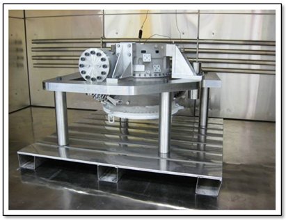
Recently, the Pratt & Whitney Rocketdyne (PWR) / NASA turbomachinery team has made significant progress toward completing the final assemblies of the hydrogen and oxygen turbopumps for the first J-2X development engine (E10001). The first two images show two major milestones for the liquid oxygen turbopump. In the first picture, the turbine-end manifold (top of the photo) is shown being mated to the pump-end volute that is secured in the build dolly.

J-2X Liquid Oxygen Turbopump after Successful Turbine Manifold Installation
The second picture shows that the oxygen turbopump has now been flipped over with the pump end now near the top of the image and the turbine manifold below. It is sitting in an oven where it underwent a drying operation after successful insertion of the first-stage turbine disk and the turbopump shaft.

J-2X Liquid Oxygen Turbopump Following First Stage Turbine Disk and Shaft Installation
The hydrogen turbopump has also made good progress by completing all pump-end assembly operations and the turbine manifold installation. The first picture of the fuel turbopump below was taken after the successful assembly of the impeller into the bearing support, and subsequently that bearing support assembly being installed into the pump end volute, which has been chilled in cryogenic liquid nitrogen. The nitrogen was used to create the proper fit for the volute and the bearing support to prevent hydrogen leakage under engine operating conditions.

J-2X Liquid Hydrogen Turbopump After Successful Mating of Volute and Turbine Bearing Support
The process of (1) chilling one metal piece so cold that it shrinks, (2) heating another metal piece so warm that it expands, and (3) then fitting the two pieces together in those states is a process used throughout engine assembly on many different components. It is a means for accomplishing an “interference fit” (also called a “compression fit” or a “press fit”), which means that the two parts, machined to their appropriate tight tolerances, would otherwise not quite fit together — almost but not quite. At room temperature, the pieces would interfere with each other if you tried to push them together. The chill/heat process during assembly allows them to fit together very, very tightly.
The second fuel turbopump picture below shows the successful installation of the turbine manifold onto the turbine bearing support representing a major milestone in the assembly process.

J-2X Liquid Hydrogen Turbopump Turbine Manifold Installed Onto Bearing Support
In the beginning of this article, I told you that rocket engine turbopumps are remarkable pieces of machinery. Yet, what I have shown you in the pictures are mostly images of shiny-metal external pieces, big hulking manifolds and volutes. For reasons largely having to do with export control considerations (Rule #1: blog author does not go to prison!), I cannot show you pictures or detailed schematics of the inner workings. I can describe them by saying that on the pump side you have an inducer, which looks like a fluid screw, and that feeds an impeller for a typical centrifugal pump. On the turbine side, I can tell you that there are two rotating disks of turbine blades and, effectively, two rows of stationary blades called stators or nozzles. And in between the pump ends and the turbine ends are a series of seals that separate the two ends. Ideally, the only contact between the pump and turbine ends would be the mechanical power of the rotating shaft.
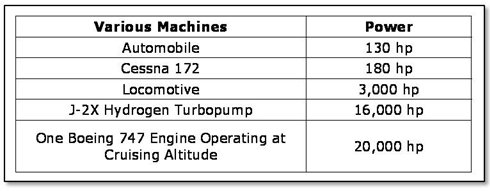
To give you a better appreciation of the “remarkable” aspects of these units, let’s consider these machines in terms of their output. In terms of horsepower, the table below compares various machines with which you are likely familiar. At only 30 inches long and 20 inches in diameter, the J-2X hydrogen turbopump produces an incredible 16,000 horsepower. This power level is equivalent to more than 120 automobiles, or 90 light aircraft, or even 5 diesel-electric locomotives. In terms of energy generated in a small package, the J-2X fuel pump provides almost as much power as a large aircraft engine on the Boeing 747.

The two turbopumps for the first J-2X development engine are currently on track to complete assembly in December. These units will then be boxed up, shipped to NASA Stennis Space Center, and await engine assembly. So, the first development engine coming soon! And then, it’s on to testing!
Note that thanks are due to Jeff Thornburg, Upper Stage Engine Element Deputy Turbomachinery Subsystem Manager, for providing the largest portion of the technical updates and pictures that informed this article.


