J-2X Progress: Engine Assembly Starts!


Ready…
Set…
Go!!!

After so many requirements reviews and concept reviews and safety reviews and design reviews, and after so many trade studies and analyses and assessments, and after so much paperwork generation and processing, and after so many programmatic meetings and technical interchanges and integration exchanges and formal boards, after all that, we have finally begun assembling the very first J-2X, Engine 10001, at the NASA Stennis Space Center (SSC) in Building 9101.

In the end, truly, it all comes to this: the hardware.  Everything that we do – and it is an astonishing amount of work – comes down to an operational piece of space launch hardware, a rocket engine (albeit a development unit first example).  It is sometimes quite easy to forget that fact after being buried in the mountains of necessary details for several years.  Yet that day has now arrived.

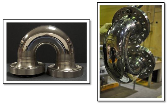
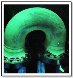
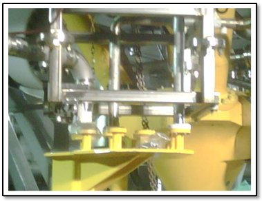
The Main Combustion Element (MCE), consisting of the Main Combustion Chamber (MCC) and the Main Injector (MI) mated together, arrived at NASA on 22 February 2011.  While a number of piece parts and components have been arriving at SSC for weeks, it is the arrival of this sub-assembly that marks the start of assembly.  It would not be too much of stretch to say that the rest of the engine, one way or another, hangs off the MCE.  So you need that part to get the whole process started in earnest.

The drawing below shows the first steps in stacking the whole thing together.


Your first question should be, “What’s a Birdcage?”  It’s actually a simulator for the nozzle.  Because this is the first build of the engine and because the various components are not completing fabrication in the optimal sequence, we have found ways to expedite engine assembly such as the use of this nozzle simulator.  The whole engine will be stacked and assembled with the Birdcage acting as the effective pedestal for the process.  Then, when the nozzle does arrive, the assembled upper part of the engine will be lifted, the Birdcage will be removed, and then the assembled pieces will be lowered onto the actual nozzle assembly to be used for Engine 10001.  Below is a photograph of the actual Birdcage sitting in its packing box at NASA SSC.

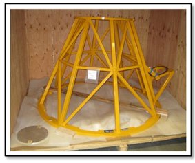
(Now, I’m not going to burst anyone’s bubble, but whoever first started calling this thing a “Birdcage” perhaps has a frightening impression of how large are the birds of southern Mississippi.  Those are some awfully large holes.)  Later, the Birdcage will be reused as the structural foundation for the assembly of the J-2X PowerPack Assembly to be tested next year.

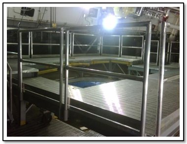
The next picture is of the assembly area where the whole thing will be brought together.  There is a raised floor on which the technicians will stand and there is a recessed area where the dolly will fit on which the engine is assembled.  On the silvery metal carts shown – the so-called “bread carts” – the kits will be laid out for the next stage of assembly as the engine comes together.

One interesting little note about that picture of the assembly area is that in the upper left-hand corner you can see another engine within a big yellow piece of ground support equipment.  That is an RS-68 engine that flies on the Delta IV vehicle.  The J-2X assembly area sits right next to the RS-68 assembly area though they are distinctly separated.

Here are some other really cool pics:

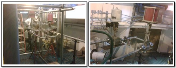
Okay, so maybe “really cool” is a slight exaggeration.  On the left is a corner of the kit staging area where, on a pallet in the back (can you see it?), sits the first pre-arranged kit of engine parts to arrive at NASA SSC.  On the right are the two turbopumps for Engine 10001 still sitting in their shipping crates.  Trust me, as the assembly process moves forward, the pictures will get better.  Really.

So, J-2X is coming together.  Over the next several weeks, I will be posting pictures and descriptions of the process.  I do have to say, from a personal perspective, seeing this thing finally becoming a reality is quite gratifying.  Thank you all for coming along and sharing the ride.


J-2X Extra: Shiny Metal Pieces


Finally, it has been discovered: Proof that rocket engineers can indeed have a sense of humor.  This is an exchange that actually happened in a meeting here at NASA not too long ago.

Manager #1: What are those feedlines made of?
Manager #2: Really shiny metal.

Translation: He didn’t know, but he would find out.  Okay, so it’s not Saturday Night Live material, but it was funny in context.  (You had to be there…really.)

The truth is that we use lots and lots of different kinds of shiny metal in all kinds of strange shapes, under all kinds of severe conditions, and with uncompromising standards against failure.  We use aluminum and steel and titanium and copper alloys and nickel-based super alloys and, sometimes, rare earth metals and precious metals.  We cast it, forge it, roll it, spin it, weld it, you name it.  Suffice it to say that if you like or know something about metal working or machining or welding or metallurgy, then even if you haven’t got a clue about rockets, we’ve probably still got a place for you.  It’s a fascinating field that ranges from enormous factory tooling necessary for large structures production all of the way down to microscopic crystal formations deep within the parts being produced.

Now, the pursuit of new technology demonstrations has never been a primary objective for the J-2X development effort.  We are supposed to make it work – that’s the prime directive.  However, in the course of J-2X development, we came across a situation where we were forced to consider innovative solutions and, from that consideration, identified an opportunity to pursue something really pretty cool and it has to do with shiny metal.


So let’s start at the beginning.  In order to avoid combustion instabilities in the gas generator assembly, we found that we needed a very short gas generator discharge duct.  What is a combustion instability?  In this case, think of a pipe organ.  The size of the pipe determines the pitch.  Big pipes make big booming sounds.  Little pipes make little whistling sounds.  What we found through component testing was that the pipe connected to the gas generator was acting like a pipe from a pipe organ and the sound was so big and so loud that it had the potential of ripping the whole thing apart.  To find a place where we were de-tuned from the booming loud vibrations, we had to make the pipe quite short. 


Now, though, we had a problem.  We had a duct so short that it basically looks like a U as pictured in the drawing above.  Note, however, that the unit used on the engine is welded on one end and flanged on the other.   This picture is a drawing of the test configuration.  But regardless of the flanges and such on the ends, this part is basically U made out of very high-strength “shiny metal” (a nickel-based super alloy).  Given the diameter of the tube, the strength of the metal, the thickness of the walls, and the fact that we can’t allow the walls to get too thin from bending, we had a devil of a manufacturing situation for what looks like, on the surface, a relatively simple component.  So, we (and that’s the big “we” of both NASA and our prime contractor, “Pratt & Whitney Rocketdyne”) started looking for solutions.

Below is a picture of the baseline solution illustrated with a manufacturing demonstration unit.  Rather than trying to do the whole bend in one piece, it is done in three pieces, each with a 60-degree piece of the overall 180-degree bend.  Those three pieces are then welded together; the end pieces are trimmed back; and the flange is welded on the end.  It works.  But it is labor intensive with all that welding and with all of work that comes along with welding along the lines of inspections and re-work cycles.  To give you an idea of size here, the duct is 3.5 inches in diameter so it is a healthy hunk of metal.


Now comes the really interesting part.

In addition to the baseline solution, another solution was proposed.  It’s called “Direct Metal Laser Sintering” or DMLS.  The company that does this is called Morris Technologies (look them up!).  And, like most high-tech stuff, if I knew the nitty-gritty details I wouldn’t be able to share them, but I can tell you the basics.  First, you start with a whole bunch of very fine metal powder.  Next, you load into the computer your three-dimensional CAD model for the part you want to make.  The CAD model is analytically cut into thousands of horizontal slices.  Then, in a special, automated chamber, a thin layer of metal powder is laid out and fused by a laser into the shape of the first slice of from your CAD model.  Then another layer of powder and fused slice is added, and then another, and then another.  With each slice, a layer of powder is laid out and fused to the previous layer precisely duplicating your CAD model a little bit at a time.  So, any shape that can be decomposed into and built up from a series of thin layers can be made.  Below is a picture of a small pump impeller with a relatively complex geometry that was made by Morris Technologies using this process.


Ignoring how it works, you’ve got this:  you put in your computer model; you put in the powder; come back a week later; and, your part is cooked (actually there are post-process surface finishing operations, but that’s just a minor detail).  It’s almost like something from The Jetsons cartoon series. 

So, we asked, can you make our U-shaped tube?  The answer was: almost.  The size limitations of the existing chamber dictated that we could do the whole tube part but the flanges would have to be welded on.  Still, it’s a pretty good demonstration.  Below, you can see a couple of pictures of the finished part.


But that’s not the end.  So, we made a fancy pipe.  Big deal.

Here is the big deal: making it was very cheap and very fast.  Of course, cheap isn’t always helpful if the thing doesn’t work.  So, we have to prove that it works.  Towards that end, we are performing materials properties tests on samples made in the chamber simultaneously with the duct, we are doing non-destructive evaluations of the duct itself, and we plan to incorporate it into a component level test series of the workhorse gas generator.  Below is a kind of creepy picture of the duct after it was inspected for tiny flaws using a fluorescent penetrant solution and ultra-violet light. 


Because of the severe environments that this duct will see, the material properties throughout the duct have to be consistently good.  There can’t be any flaws on the surface that could lead to the development of cracks.  So far, the piece has come through all of the inspections with flying colors.  The next step will be actual hot-fire testing.  Below is a photograph of previous testing of the workhorse gas generator.


If everything goes well and post-test inspections show that the part did not sustain damage, we will have taken a huge step towards making this fabrication approach viable for not only this particular piece of the J-2X engine, but for all kinds of parts on all rocket engines in the future.  There are technology issues to overcome – notably current limitations on the size of the parts to be made – but this process is potentially an order of magnitude improvement in terms of the costs for building complex, severe environment components out of that ubiquitous substance that we’ve got all over in a rocket engine, i.e., “shiny metal.”


J-2X Progress: Test Stands Moving Towards Readiness

In the broadest sense, stepping back from the project, the J-2X development effort has three primary branches.  First, of course, you have our prime contractor, Pratt & Whitney Rocketdyne (PWR) who is responsible for designing the engine and demonstrating that it meets the imposed requirements.  Second, you have the team here at NASA responsible for management, technical oversight and insight, and, in a handful of specific cases, mainline work in support of PWR activities.  And, third, you have the extensive efforts underway at the NASA Stennis Space Center (SSC) in southern Mississippi to provide a site for testing of the J-2X.  If you scroll down a ways through previous articles you’ll see that I wrote an overview article about SSC and the test stands there.  Here, for this article, I’m going to provide an update and show off some neato pictures of the ongoing work.

The first engine testing will take place on stand A2.  In the picture below, technicians are using a locator tool to properly position the water spray ring to where it will need to be over the diffuser.  The water spray ring is used to cool the top portions of the diffuser and is necessary since the first tests of the engine will not have any nozzle extension attached below the regeneratively-cooled nozzle.  This means that the exhaust flow will not be entirely ‘turned’ and so it will impinge on the diffuser walls. 

Next, after getting the spray ring close to the correct position using this tooling, the diffuser will be raised into position below the ring and a laser measurement system will be used to determine the exact location of the spray ring.  At that point, the support arms will be installed so as to maintain that position.

In order to check out the extensive communications between the test control center, the test stand, and the engine itself, PWR shipped to SSC the first prototype engine controller.  In the picture below what you see is the controller actually sitting on the test stand, on the same level where the engine will be during testing, talking back and forth with the stand.  Of course, once the engine arrives, it will have its own controller mounted to the engine itself.  This one is just being used for check-outs.  Getting all such things checked out and running properly prior to installing the engine is crucial if you harbor any hopes of maintaining your schedule.  This is a fine example of PWR and the crews at SSC working together towards a common goal.

When an engine is being tested, the area around it is pretty much cleared away.  Almost anything close would be swept into the exhaust, or rattled apart, or melted from the heat in the plume.  It’s truly a violent environment.  But before and after the test, you need to be able to get your hands on the engine for a whole variety of reasons.  For example: After a test, the engine needs to be dried.  Remember that the combustion product for an oxygen-hydrogen engine is hot steam.  When the engine cools after a test, that steam condenses and becomes water.  In order to prepare for the next test, we have to dry out all that residual water and we do so by blowing heated gas, dry air or nitrogen, through the engine.  So, we need access to the engine to hook up the hoses. 

In the picture above are shown the lightweight, temporary platforms that have been created to allow for engine access.  The engine will reside in the hole in the middle of the platforms.  Prior to a test, these platforms are removed and after a test they are erected back in the position shown.

Okay, now we’re going to move over to the work being done on test stand A1.  This is where we will first be testing the PowerPack Assembly (PPA).  The PPA primarily consists of the turbomachinery and the gas-generator.  It is essentially a special test bed for the propellant feed and turbine drive functions of the engine.  Because the PPA does not have to feed a carefully balanced engine system and because we will be using special test equipment electro-mechanically activated, EMA, valves to control the PPA, we will have the freedom and ability to explore many more operational conditions for the turbomachinery than are possible during actual engine testing.  This is a way to truly wring out the design with only a limited number of test articles.  We will be calling the upcoming test article PPA2 since we had previously tested a PowerPack Assembly composed of legacy J-2S and XRS-2200 components back in 2007 and 2008.  After PPA2 testing, test stand A1 will be converted back to a full engine test facility.


Just as we are using an engine controller to check out the communication systems, and just as we have special tooling for finding the right location for the spray ring on test stand A2, a special tool was developed by PWR to help the technicians at SSC properly position all of the plumbing that feeds into the engine.  The tool is called a Master Interface Tool (MIT) and it is simply a bunch of fake interfaces all in the correct geometrical locations as though they were the real interfaces for an engine and PPA2.  In the picture below, the MIT is the yellow item in the foreground.  This portion of the MIT simulates the connections for all of the ancillary lines to the engine besides the main propellant flows.

Because the MIT properly emulates the engine, once all of the piping on the test stand side meets up with the tool, the technicians have much greater assurance that when an engine shows up, it will fit into the space provided.  This is a much better approach than attempting to locate these lines in space with no solid reference point and it saves time since these lines can be installed now rather than waiting for the engine or the PPA2 to show up on the stand.

The MIT appears in the picture below as well.  It is the yellow item on the bottom and here it is being used to position the installation of the liquid hydrogen and liquid oxygen feed lines.  Thus, when we are actually up and running with an engine, it will hang right where the MIT is currently sitting.

The other yellow items in this picture, the beams that appear to extend up and into the rafters, are the structure that carries the thrust of the engine.  These four beams will transmit a total of approximately a quarter of a million pounds-force of thrust into the thrust measurement system and into the test stand itself.

The last couple of pictures that I wanted to include here is intentionally less ‘glamorous’ than some of the previous ones showing where the engine will sit when tested or big pieces of tooling, etc.  These pictures were taken in a couple of corners of the A1 test stand on the deck above where the engine will sit.  These are the piping systems that will control and measure what on the vehicle would be the tank pressurization flows coming off the engine. 

The intended point about these last two pictures is that the facilities necessary to properly test a rocket engine are quite involved and quite complex.  The environments are vicious, the tolerances are tight, and everything that goes into or comes out of the engine needs to be controlled and measured.  Indeed, the whole reason for doing engine testing is to gather data so as to better understand how well the design works.

Work continues.  The formal Facility Readiness Reviews for these stands are currently scheduled for early March for test stand A2 and late April for test stand A1.