It’s been about three weeks since I last reported on the progress of J-2X Engine 10001 assembly. What I would like to do is show you pictures of great big additions to the engine, but the truth is that for the last few weeks the engineers and technicians have been diligently plugging away at smaller stuff, at the details.
“It’s the little details that are vital. Little things make big things happen.” – John Wooden
I would hazard to guess that Coach Wooden was talking about basketball – or maybe life in general – when he spoke these words, but on a rocket engine, everything has to work so the details of the big stuff and of the little stuff are equally vital.
So, here are some pictures and some details…

We’ll start with a picture of the overall assembly and the addition of the item in the dashed, red oval on the right-hand side of the picture. That is the gas generator. Yep, that little thing powers both turbopumps and therefore is the driving force behind the whole engine. Here is a closer picture.
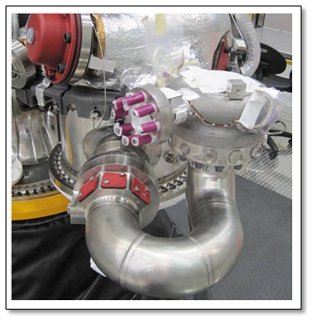
As I’ve mentioned before, during the whole assembly process, things either have covers attached or are wrapped in tape and other protective media so that no debris gets in the engine and so that delicate parts are not damaged. You can see that here on the gas generator.
Note that in the image of the gas generator above, you will see the “U-duct” from an earlier blog series entry regarding Direct Metal Laser Sintering. This, right here on the engine, is the piece for which we may have found a future innovative manufacturing method.
Next is a picture of a mounting plate. This is not even a primary piece of the engine if you were looking at a schematic, but it’s a vital piece nonetheless. On this mounting panel sits the two Main Injector Exciter Units (MIEUs). An MIEU is analogous to the ignition coil in your automobile engine but with a good bit more punch. We use two units for redundancy to further ensure overall reliability. If, in the morning, your ignition coil goes dead in your station wagon, well you’re just stuck in your driveway. However, if during a launch mission you can’t get the J-2X started, then you’re stuck somewhere over the Atlantic Ocean at two or three hundred thousand feet. That’s a somewhat more treacherous situation. So we use very highly reliable parts and we use two parallel units.
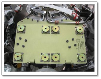
What makes this mounting plate interesting is that it has vibration isolators so that the noise and shaking of the engine don’t impact the electrical components of the units. Those eight circles on the mounting plate are the tops of the isolators so there are four for each unit. Kinda cool little details.
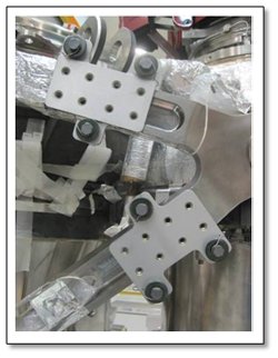
Next, more mounts. In the picture below, you will see two rectangular items, each with eight holes. These are mounts on which will eventually reside pressure transducers. There are several such transducer mounts across the engine. These particular mounts are installed on the arms that hold the oxidizer turbopump. So, we have mounts installed on mounts and you can begin to understand the complex layering that an engine assembly represents.
One strategy that is used quite often during the assembly process is to do stuff unattached from the main assembly itself. Over on a separate bench, you put together a bunch of smaller pieces and then take this whole subassembly over to the engine for installation. Over the past couple of weeks, this is exactly what has been done with the ancillary line “raceway.” Below is the completed raceway subassembly.
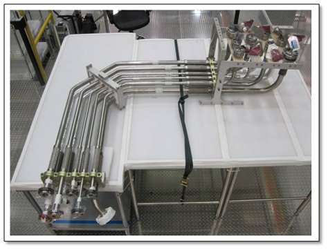
All of the lines and brackets and nuts and bolts were separate pieces when the engineers and technicians began.
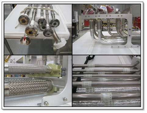
Each line in that assembly is different since each line represents different fluids coming to or coming from the engine at different pressures and temperatures. There is helium, oxygen, hydrogen, and even nitrogen. There are pressures over 3,000 psi and less than 50 psi. There are temperatures approaching the boiling point of water and those less than 400 degrees below zero Fahrenheit. Thus, some of these lines shrink from the cold. Some of them stiffen with high pressure. Yet all of them have to be flexible to accommodate the gimballing of the engine and every one of them is vital either to the engine or to the vehicle. In other words, it is a complex design, a complex manufacturing process, and a complex subassembly to put together. And it all has to be correct. Details, details, details!
Lastly, I’d like to toss in a cool picture from the test stand. Below is a picture from test stand A-2, with the engine mass simulator installed. This is where J-2X Engine 10001 will be tested. The brightly painted, yellow hunk of metal is supposed to weigh the same as a J-2X and have the same dimensions. It’s used for checkouts of various systems including the test stand.
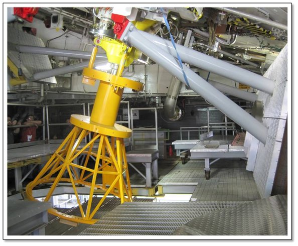
Another thing of note in that picture from A-2 is large gray object to the right. That is half of a water-spray system that will be used during testing when no nozzle extension is installed on the engine. Near the top of the picture is a hinge painted bright red. When deployed, the gray water-spray structure will have been swung down so that its two pieces (the one shown and the other one to the left and out of the picture) join at the bottom of the engine nozzle. This is all part of the system to deal with the substantial, combustible, fast moving, and very hot exhaust from the engine during test. This water-spray system was installed specifically for J-2X testing.
That’s where we stand. The details of the engine assembly are coming together, with more parts arriving at the NASA Stennis Space Center every day, and with the test stand is being readied to accept installation of the engine. This is Volume 4 of the assembly saga. By the time Volume 5 is ready for the blog, we should be very close to having a fully assembled engine. Wahoo!


