The first car that I ever owned was a “goldenrod” 1974 Ford Pinto. My uncle Johnny was a car salesman for Buick at the time. He sold new, bright, and shiny machines in his showroom, but, of course, they took in trades of all shapes and sizes and conditions, many of which they would not dare put back on their own lot. My little Pinto was just such a vehicle. I bought it from the obscure and hidden back lot for $500 with absolutely, positively no guarantee that it would continue running until the end of the week. While it was only eight years old, back then (sad to say) autos simply didn’t last as long as they seem to today, particularly if driven hard in the weather of the northeast. So I spent months and months of afterschool hours and weekends replacing rusted panels and floorboards with broad swaths of fiberglass. Also, despite the fact that I was never a true gear-head, I was able to open up the hood and do some work on the engine. It was a straight four cylinders and as simple as could be. You could reach into the engine compartment and easily find and touch just about every greasy major component.

Just a couple of years later, my mother bought a new Saab. When I opened the hood of that sleek machine, I couldn’t find anything. The engine was turned sideways, apparently, and the compartment was completely stuffed to the gills with overly clean, boxed-up things that I couldn’t identify, and lines zigging and zagging in all directions. It was fuel-injected and front-wheel-drive and all kinds of other jet-engine craziness that my cozy little, oil-burning Pinto was not. So I closed the hood of that pretty blue Saab and I decided that I’d never make it as a modern mechanic.
Why am I bringing this up? Because some of the latest pictures from the assembly of J-2X Engine 10001 reminded me of my confusion in looking under the hood of my mother’s car. Only much worse. Yikes.
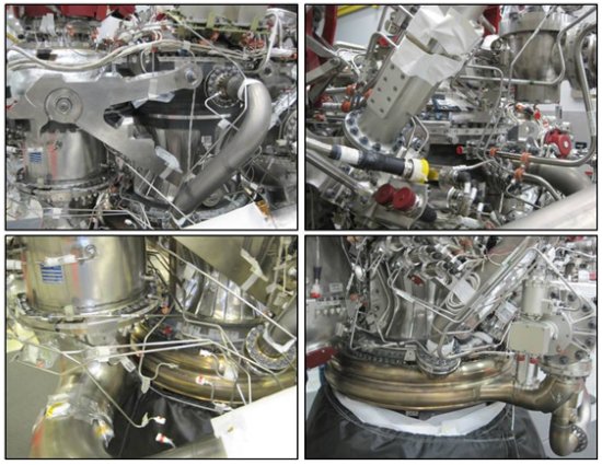
I’ll get to the progress we’ve made with the big pieces, but first I want to talk briefly about what looks like a chaotic explosion of confusing stuff all over the engine pictures. I will begin by telling you a secret: There are two reasons that we test rocket engines. First, we test rocket engines so as to impress our friends, most of whom are geek engineers like ourselves or people otherwise excited by loud noises made by neato, exotic machines (i.e., lots of NASCAR fans).
Second, we test rocket engines to gather data. Lots and lots of data. Many gigabytes of data. We measure pressures, temperatures, rotational speeds, flow rates, and dynamic vibrations both in terms of acceleration and in terms of strain. As part of the development program, we test in order to prove that what we thought was true when we created and analyzed the design is in fact true with the real hardware. And anywhere where we were mistaken, we need to know as quickly as possible so that we can recalculate our margins of safety and, if necessary, make adjustments to the design for the next development engine to be tested. Testing rocket engines is not cheap, and, of course, neither are the engines themselves, but we need to acquire this thorough, unassailable understanding of the engine long before we would ever imagine strapping a human life to something with such awesome power.
This need for data explains much of the “bloom” of seemingly ten thousand little lines and wires snaking hither and yon all over the engine. Some of these small lines carry pneumatic pressure for actuating valves or providing purges, but lots of them are related to the many, many measurements we’ll be taking during the upcoming hot-fire test series. In fact, these early development engines will be far more heavily instrumented than any engine we would ever fly because, again, their whole purpose to generate useful data (well, that and to impress our friends). What is truly amazing to realize is the fact that every one of these lines has a specific shape and route; every one of these lines is designed, not randomly configured; and every one of these lines represents a documented step in the assembly process.
Now to the big stuff.
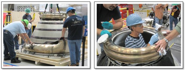
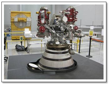
The first big assembly news to share was the arrival of the regeneratively-cooled portion of the nozzle (usually called the “regen nozzle” around here). In the pictures above, on the left you can see the assembly technicians preparing to lift the regen nozzle out of its shipping container. On the right is a picture of some preparations being made to the nozzle before the rest of the engine is stacked on top. If you’ll remember, the rest of the engine was previously being assembled on a simulator of the nozzle. Interesting little side note: In order for the technician to get into the position you see in the picture on the right, she had to crawl under the elevated assembly platform and stand up inside the nozzle. In the picture below you can see the stack of the engine on the actual regen nozzle.
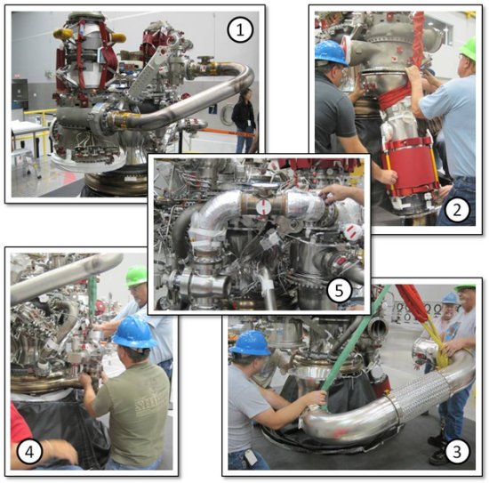
Now, with the regen nozzle in place, lots more stuff could be added to the assembly. In the collage below, five big items are shown in the process of installation: (1) the liquid oxygen pump discharge duct that carries liquid oxygen from the pump to the main oxidizer valve, (2) the oxidizer turbine discharge duct that contains within it the helium heat exchanger, (3) the turbine cross-over duct that carries hot turbine drive gas from the hydrogen turbopump turbine outlet to the oxidizer turbopump turbine inlet, (4) the main fuel valve, and (5) the fuel pump discharge duct that carries liquid hydrogen from the fuel pump to the main fuel valve.
And that’s just a small sampling of the flurry of assembly activity over the last few weeks. I like the fact that I was able to include pictures showing some of the folks working hard to get this thing put together. They’re doing an extraordinary job. The result of all this work is something that is really, truly starting to look like a rocket engine. The pictures below show what you’d see if you took a casual stroll around the engine. Note that the regen nozzle is covered with a black, protective tarp and there are other protective coverings all over the engine, so this isn’t quite as gorgeous as it could be, but for us rocket geeks it’s awfully compelling.
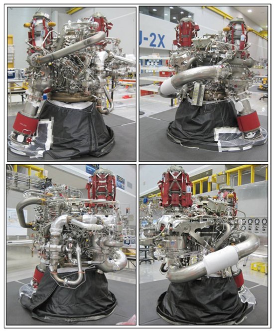
So, that’s where the engine stands. Almost all of the big stuff is installed, with just a couple of notable exceptions. Additionally, lots and lots of little stuff has also been installed. Over the past few weeks, it’s come a long, long way. As a reminder, take a look at this:
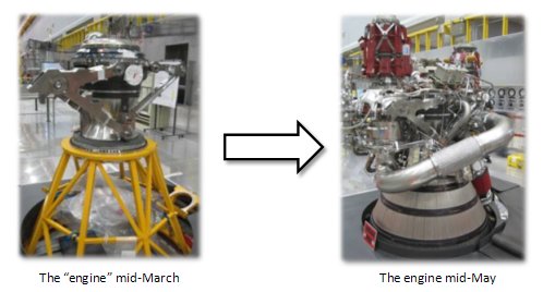
But, then, I guess everything eventually comes a long way with a little bit of hard work. Take, for example, how I’ve been blessed to evolve through the years:

With all due respect to the Ford Motor Company and their venerable line of Pinto automobiles, that’s one heck of a leap even if it did take a long time. I just bet that my Uncle Johnny would be proud to think that he was there at the start of the whole thing.

Good pictures. Did not realize how relatively small the combustion chamber becomes when all the other stuff is attached.
There’s an old axiom that gearheads use. To determine just how difficult an engine is to work on, take a dollar’s worth of pennies and toss them in the engine bay. The fewer pennies that hit the ground, the harder the engine is to work on 🙂
Judging by those pictures, not a single penny would hit the ground. Ever. Even if you shook the engine around for a while.
It’s great to see this whole project coming together piece by piece. I can’t wait for the next update! 🙂