Put a little kid into the driver’s seat of a (safely parked) car and what’s the first thing that they do? They grab the steering wheel and twist it back and forth. Twisting the steering wheel back and forth is just about the most intuitive, intrinsic — practically instinctive — sense of “driving” that I can imagine. Even the handlebars of a bicycle or a motorcycle fit into the same idea. Can you think of driving a car or a boat or, well, anything, without a steering wheel (of some sort)? It’s tough, isn’t it?
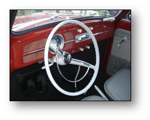
Okay, now think of a launch vehicle blasting off the pad and upwards heading towards the sky. Other than for some extreme, emergency conditions, there is not anything that stands in for the steering wheel on a launch vehicle during ascent. The process of steering the vehicle requires such precision and responsiveness that it has to be automated. Sorry Buck Rogers, the computer is flying the vehicle. But, even without a steering wheel, per se, how does steering happen?
With a car, you point the front wheels and, thanks to friction between the tires and the road, you get pulled (or pushed for the sports car purist and NASCAR fans) in that direction.
With a boat, you use a rudder so that the water pushing against it points the boat in the direction you want to head.
With an airplane, you have to use a combination of aerodynamic surfaces since you’re now dealing with steering in three dimensions, not just two as with an automobile or a boat. But the idea is basically the same: the air through which you’re moving pushes against the aerodynamic surfaces and points the plane in the direction you need to go.
What do you do with a launch vehicle? Not long after the first couple minutes of flight, you’re so high in the atmosphere that there’s not enough air to effectively use aerodynamic surfaces. In other words, you don’t have a road and a rudder won’t work. So what do you use when you don’t have anything against which to push? That’s right: a rocket!
You could, if you chose to do it this way, use dedicated steering rockets. We do use these when we’re in space and we typically call them “retrorockets” or “reaction and control” rockets. But during the ascent, you already have a big rocket engine pushing you along so you might as well use that if you can, but to do so, you need to twist it around…

[Yes, I can’t help myself. I had to make a musical reference. “Twist and Shout” (written by Phil Medley and Bert Russell) was originally recorded by the Top Notes, then the Isley Brothers, and, eventually by the Beatles (as so memorably replayed many years later in “Ferris Bueller’s Day Off”). Lots and lots of people have done versions of this song, but probably the most bizarre was Mae West — yes, THAT Mae West — when she was 72 years old. Who knew?]
What do I mean with regards to twisting a rocket engine? Here’s a video of what we call “gimballing” an engine on the test stand, in this case a Space Shuttle Main Engine (video provided by my friend and coworker Rick Ballard from his Liquid Rocket Engine class materials):
So, for a launch vehicle during ascent, you accomplish steering by pointing the thing pushing you, i.e., your main propulsion rocket engine. That’s a cool video, huh? But how do we accomplish that? The movement itself is provided by hydraulic actuators. These are push/pull devices driven by fluid pressure. The brakes on your car are hydraulically actuated, for example. Another example of hydraulic actuators are those lifts at the garage they use to pick your car up off the ground. In other words, they can be very powerful devices. You can do a quick web search on “hydraulic actuators” and find all kinds of pictures and articles and even sales pitches from manufacturers.

On the rocket engine we put just two connection points for the actuators at ninety degrees apart from each other. This gives us what you can think of as full, two-dimensional coverage. If you remember back to math class, everything on a flat page can be located via X-Y coordinates. Thus, one actuator provides the X-direction and the other provides the Y-direction. And, with that, we can point the engine to any location within a given, limited range of movement.
At the top of the engine, in order to allow the movement, we put in what amounts to a universal joint. It’s called the “gimbal bearing” and it’s like the ball-and-socket joint in your shoulder except that this joint has to carry the full thrust load of the engine while maintaining its flexibility. Because of the conditions seen by the engine, you can’t use any typical lubrication like grease or anything like that. Instead, we use a Teflon-impregnated fabric layer.
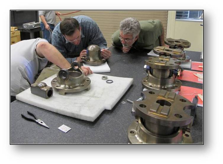
I like the picture above showing several guys working with typical engine gimbal bearings. In the picture you can get a sense of how beefy these things are when assembled and you can clearly see the “ball” part of the ball-and-socket joint.
Have we gotten to the really, really neato part yet? Yes, we have (in my humble opinion). Here it comes. How is it that we can move around the engine? I mean, besides the big ball-and-socket joint at the top that is meant to move around, all the rest of it is assembled out of all kinds of stiff metal pieces, right? It’s not like you can stick cryogenic propellants through a flexible rubber garden hose. So how do we get the compliance in the rest of the engine components that allow for the movement the actuators and gimbal bearing are providing? With no compliance, the actuators would push and pull, and, assuming that they were powerful enough to do damage (and they usually are), the engine ducts would buckle and crush and, frankly, you’d have a crumpled mess. What we do then is build the compliance into the engine with specific parts to provide this functionality. This is accomplished in different ways on different engines. Below is how this compliance is accomplished for J-2X for the main propellant lines:
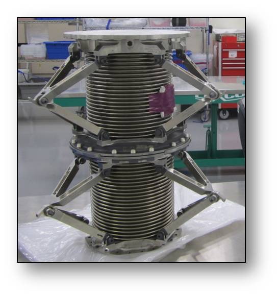
That pretty piece of hardware is a propellant inlet duct. In fact, that picture is of the first new propellant inlet duct fabricated for a J-2, J-2S, or J-2X engine in forty years. This new duct is like the heritage design but better, safer, more robust. It is an extremely difficult piece of hardware to make in that it involves some very highly specialized welding techniques. So a big shout-out goes to Pratt & Whitney Rocketdyne and the guys on the shop floor. Way to go guys!
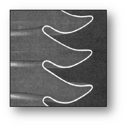
How does it work? The sections with the convolutions are called bellows. Above is a cut-away of a metal bellows made by the same company as our propellant inlet duct, Gardner Bellows Corporation, but not our same design. The bellows take advantage of the way that metal can act like a spring. If it doesn’t get bent too far, the metal will bounce back undamaged. These dozens of convolutions in the bellows allow for enough movement that the whole thing acts like a stiff spring. The hinged structures on the sides hold the bellows together and constrain the springy parts and make sure that they stay in their groove (so to speak).
The next natural question about this duct is this: Why does it appear to be in two pieces, an upper bellows and a lower bellows? The answer is that it isn’t in two pieces; it’s in three pieces. In between the upper bellows and the lower bellows is a third set of bellows that you can’t see very well and that’s because they’re really flat. This is the torsional bellows and it provides for a slight twist between the upper and lower sections. When you’re gimballing the engine, not only do you need these ducts to bend, you also need a bit of twist…
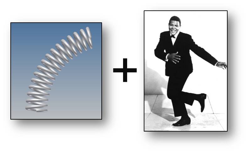
I think that the torsional bellows is even cooler than the bending bellows. Have you ever tried to twist a long piece of wood, like maybe an eight-foot-long, one-by-two strip? The longer the piece, the easier it is to get a few degrees of twist. A short piece of wood, even with the same cross-sectional dimensions, won’t allow for as much twist. There is an “allowable twist per unit length” thing going on: longer = more twist, shorter=less twist. Okay, now assume that the same is true for a metal pipe. If you have a very long metal pipe and you apply a twisting force to it (torsion), you can get some movement, more movement than you’d get with a short pipe. But there’s no space on a rocket engine for a very long pipe, so how do you allow for some twist? What we do is collapse the long pipe into shortness by making it into a very tight accordion-like package. In other words, we add convolutions kind of like the bending bellows, but make them very tight, very flat. So, all of the metal “length” is still there, just in a really compact, squashed package. It kind of feels like cheating, somehow, but it works. See?! That’s just neato!
In addition to the big ducts, the propellant ducts, you also have to take into account any other connections between the engine and the vehicle stage. If you think back to the article about vehicle integration, you’ll remember that we’ve got pneumatic lines and propellant pressurization lines and helium spin start lines connecting the engine to the stage. In all of these lines we have to make provisions for compliance to engine gimballing motion. As you can imagine, this makes the design for these pieces not simple. But nobody ever said that rocket engines were supposed to be simple. Also note that different rocket engines use different approaches for achieving the compliance necessary to accommodate gimballing, but they almost always use “springy” metal bellows in some sort of configuration.
The first J-2X engine that will see gimballing in the test stand will be development engine E10002. That should be happening later this year. Stay tuned. I’ll certainly be posting some gee-whiz video after that happens. Go J-2X!

What alloy (or alloys) are the propellant inlet ducts? Nice that they remain flexible at LH2 temperatures.
Thanks. This is excellent. I’ll use it with my Rockets class at Front Range Christian School (http://yourhub.denverpost.com/def-section/soaring-heavens/9RZY0y6Fwe1cO15RAoEgyM-ugc)
@Jeff: Just about 90% of the engine overall, give or take, is made of nickel-based super alloys 625 and 718. In the case of the inlet ducts, both alloys are used to make the final assembly. These alloys are used throughout the aerospace industry and are certainly not unique to J-2X or even to rocket engines in general. But they are darn good materials.
FYI, something else that I should have mentioned about the J-2X inlet ducts is that the one on the liquid hydrogen side is actually composed of two walls with a vacuum in between. This is like a Thermos (TM) bottle and is necessary so that we don’t get ice built up on the ducts. The convolutions don’t work so well when they’re gunked up with ice. In this case the “ice” wouldn’t be water ice, but solid nitrogen pulled out of the purged atmosphere of the inter-tank section of the vehicle. This double-wall, vacuum-jacketed approach is not necessary on the liquid oxygen side since the freezing point of nitrogen is far below the temperature of liquid oxygen.
Fun with cryogens!
This is very interesting and impressive but I can see possible defects I would not really deem it safe to use as the production quality of the molecular structure of the material used for the main flexi pipe can not be 100% guarantied 100% of the time therefore it is doomed to fail at some point and obviously a leak in the flexi pipe would effect the guidance etc. The best way to steer a rocket is to have four separate thrusters set at 45 degrees these are placed just below the nose and constantly fire at 50% but instantly adjust to guidance, these can also be used to make the rocket lean to one side and rotate, this is much safer and reliable. Also the nose of a rocket is better being a sphere that has a width of half as much as the rocket fuselage, this is because a as the air passes over the sphere it will actually pull it up instead of the traditional cone nose which actually is very good aero dynamically
@Peter: Nothing can be guaranteed 100%. Anything can break. But this is how we’ve been using rocket engines for about 50 or 60 years now so we’ve figured out a few things.
First, there is the design. The component is designed with the appropriate margins for structural strength and fatigue considerations. It is analyzed to identify potential high stress areas and those issues are mitigated. Second, the component is inspected throughout the fabrication process. Every piece part, every weld, every joint, everything is inspected for workmanship and defects as it moves through the process. And, third, we demonstrate the heck out of the component through the engine development and certification test campaign. A new flight engine off of the production line will be expected to see maybe seven or eight engine starts and a few thousand seconds of operational time. During the development and certification test campaign, we’ll show multiple samples of these components experiencing three or four times as many starts and three or four times as much operational time. Then, after experiencing all of this usage on the development and certification engines, we typically take the used components off and inspect them, looking for signs of wear. Rocket engine development is methodical and follows stringent, long-established standards and guidelines. This can sometimes be time consuming and expensive, but failure is really not acceptable for a launch vehicle mission.
Now, having said all that, there are other ways to steer a launch vehicle. You describe something akin to reaction and control rockets. That could work, but it forces you to carry a lot of extra propellant and ancillary hardware for this additional system. Weight is always an issue in a launch vehicle. Every extra pound of vehicle that you are forced to carry into orbit is a pound of payload lost. This is the biggest reason why we usually utilize engine gimbal for steering. It’s just more efficient to your big hoss engine to push you around if you’re already using it anyway.
Another way that you could create vehicle steering, assuming that you’re using a cluster of engines, is to differentially throttle the various engines in the cluster. So long as you have at least three engines, you can cover yaw and pitch. Roll could is problematic, but then it often is depending on the configuration and number of engines. An example of differential throttling being used as a substitute for gimballing was the linear aerospike engine, XRS-2200, intended for use on the X-33 vehicle. Each XRS-2200 engine was kind of like a mini cluster of twenty little engines and each of these could be individually throttled. While this engine never flew, this concept was demonstrated on the test stand back in the 1990’s.
Why do you point the engine instead of using steering vanes in the exhaust stream to guide the vehicle?
@Steve: The reason that we don’t try to use steering vanes in the exhaust is because pointing the engine is easier than trying to solve the problem of making vanes that will survive the environment. Using an ideal chemistry equilibrium calculation, you’d find that at the exit of the full nozzle extension, the exhaust is moving at about Mach 5 with a temperature of still over 1100 degrees Fahrenheit.
What would the vanes have to be made of to survive that? Would they have to be actively cooled? How beefy would they have to be to survive the loads from the oblique shocks that they’d set up in the flow? And what about the control system to move these around? Could we truly get sufficient two-dimensional coverage as well as we do with gimballing?
Probably, if you had a lot of money and some enthusiastic engineers, we could figure it out. There’s really not much that we can’t figure out how to do given enough time, energy, and money. But since gimballing works, why would we try to solve what seems to be the harder problem? There can often be multiple solutions to technical issues. What you try to do in solving issues is find the best balance of minimizing technical risk within the programmatic constraints of schedule and budget.
Helpful answer?
Great article and, once again, thanks! 🙂
I’m guessing that those bellows cause some kind of fuel flow turbulance since fuel is flowing from a “straight pipe” to a “bellowed pipe” back to a “straight pipe”. Is there any turbulence and if so does it cause a problem?
Thanks for the explanation. I was thinking that gimbals must withstand the entire thrust of the engine and would add weight whereas steering vanes would not; also the flexible plumbing would not be necessary. The use of steering vanes is an old idea; however, the problems you point out are significant and gimballing is a proven technique.
@Aaron: At least for the SSME, (I would imagine the J-2X plumbing uses similar techniques), the flexible joints contain an integral flow liner. This liner prevents the propellant flowing through the duct from impinging on the convolutions of the bellows which could cause flow turbulence, resulting in hardware vibration. The liner is made up of two or three overlapping pieces. The outside ends of the end pieces are welded into the flexible joint so as to form a continuous, smooth internal diameter when the flexible joint is itself welded into a duct.”
Given that J-2X bellows are supported on the outside, unlike the SSME, this would help in keeping flow turbulence, and the vibrations that are induced, to a minimum as well.
@Steve: Yep, the gimbal bearings are usually quite beefy in order to withstand the thrust being driven through them, but that’s just part of the overall trade. Note that while gimballing is a proven technique, different engine designs approach even this solution in different ways.
As I’ve shown, for the J-2X, the whole engine gimbals and the accommodation is made in the propellant lines prior to entering the turbomachinery. For the SSME, the low-pressure turbomachinery is actually bolted directly to the Shuttle and the accommodation for the gimbal movement is taken up on the wrap-around ducts that feed the high-pressure pumps. For the RS-68, it’s only the thrust chamber assembly that is gimbaled so that the propellant lines after the pumps have to accommodate the motion. So, in this case, you’re flexible joints have high-pressure flow through them and not low pressure as on J-2X. The RD-180 (Russian engine design) actually has a bellows section accommodating gimbal movement in an oxygen-rich hot-gas duct.
So, the accommodation for the gimbal motion can take a variety of solutions, but the gimballing itself is pretty standards.
@Mark and Aaron: You can have convoluted bellows with or without liners. There are advantages and disadvantages to both.
The J-2X propellant inlet lines are not lined. Over the years, we have developed extensive sets of design and operational guidelines for flow through convoluted metal bellows. If you fail to follow these guidelines, you have the possibility of suffering what are called “flow-induced vibrations.” These vibrations can, in some circumstances, become destructive. There was actually an in-flight engine failure on an unmanned Saturn V launch in 1968 (Apollo 6) that was traced back to flow-induced vibrations in a small hydrogen line that fed the J-2 augmented spark igniter (i.e., not the inlet duct but another smaller line within the engine).
For the J-2X, we will be performing tests of specially instrumented inlet ducts that will, in part, be used as validation of our guidelines for their design.
Thanks for the correction!
a movement could be the intention of moving the surprise of installing the movement
consolidate a movement is movement ?
Action = ?
The beginning is not the end if we consider movement of movement pending the rules of all movement inside the movement outside movement cause interior exterior or the impulse such as controlling the movement initially oh birds of aerodynamic pause reflecting the sky like colors diferentially