It’s been a few months since we talked about J-2X development progress. So, let me bring you up to date. Here’s the short version:
- Testing for engine E10002 is complete
- Engine E10003 has been installed in test stand A-2 and has successfully completed its first test (a 50-second calibration test on 6 November)
- Engine E10004 is in fabrication
Okay, so that’s it. Any questions?
Oh, alright, I’ll share more.
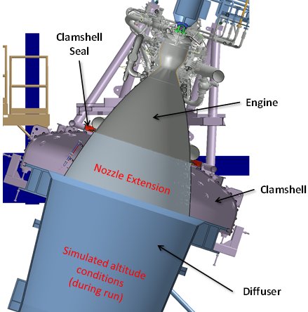
Engine E10002 is the first J-2X to be tested on both test stand A-2 and on A-1. It saw altitude-simulation testing using the passive diffuser on A-2 and it saw pure sea-level testing on A-1 during which we were able to demonstrate gimballing of the engine. Below is a cool picture from our engineering folks showing a sketch of the engine in the test position on A-2.
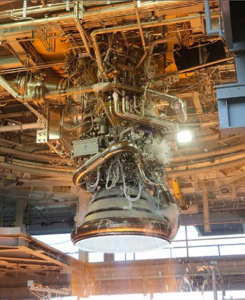
The clamshell shown in the sketch effectively wraps around the engine in two pieces and the diffuser comes up and attaches to the bottom of the clamshell. This creates an enclosed space that, while the engine is running, creates the simulated altitude conditions. I’ll show some more pictures of the clamshell when we talk about engine E10003 below. Next is a cool picture of engine E10002, hanging right out in the open, while testing on A-1.
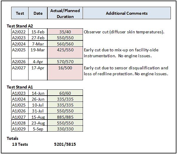
This next table gives a history of the engine E10002 test campaign across both test stands:
So, let’s talk about the three times that we didn’t get to full duration.
The first time, on test A2J022 we had an observer cut. Just like that sounds, there was actually a guy watching a screen of instrumentation output and when he saw something that violated pre-decided rules, he pushed the cut button. We use such a set-up whenever we’re doing something a little unusual. In this case, we were making an effort to reduce the amount of cooling water that is pumped into the diffuser. It was our general rule-of-thumb to “over cool” the diffuser. After all, who cares? It’s a big hunk of facility metal that we wanted to preserve for as long as possible despite the fact that it always gets a beating considering where it sits, i.e., in receiving mode for the plume from a rocket engine. However, one of the objectives for our testing was to get a good thermal mapping of the conditions on the nozzle extension. What we’d found with our E10001 testing was that all of the excess water that we were pumping into the diffuser was splashing up and making our thermal measurements practically pointless. Thus, we had to take the risk of reducing the magnitude of our diffuser cooling water. As I’ve said many times, there are only two reasons to do engine testing: collect data and impress your friends. If our data was getting messed up, then we had to try something else. Eventually, through the engine E10002 test series we were able to sufficiently reduce the diffuser cooling to the point where we obtained exceptionally good thermal data. This first test on which we cut a bit early was our first cautious step in getting comfortable with that direction.
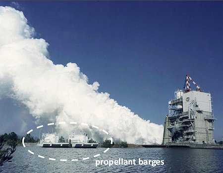
The second early cut was caused by some facility controller programming related to facility instrumentation. Here is a little tidbit of neato information that I’ve probably not shared before about our testing: in the middle of longer runs, we transfer propellant from barges at ground level upwards and into the run tanks on the stand. The run tanks are pretty big, but they’re not big enough to supply all of the propellants needed for really long tests. When I’ve shown pictures of the test stands in the past, you’ve seen the waterways that surround and connect all of the stands. These are used to move, amongst other things, barges of propellant tanks. Liquid oxygen is transferred using pumps and liquid hydrogen, being much lighter, is transferred by pressure. In the picture below, you can see a couple of propellant barges over to the left. This is an older photo of a Space Shuttle Main Engine Test on stand A-2.
Thus, in addition to monitoring the engine firing during a test, you also have to watch to make sure that the propellant transfer is happening properly. The last thing that you want to happen is have your engine run out of propellants in the middle of a hot fire test. On test A2J025, there was an input error in the software that monitors some of the key parameters for propellant transfer. Thus, a limit was tripped that shouldn’t have been tripped and the facility told the engine to shut down. Other than some lost data towards the end of this test (data that was picked up on subsequent testing), no harm was done.
On test A2J027, there was something of an oddball situation. We have redlines on the engine. What that means is that we have specific measurements that we monitor to make sure that the engine is functioning properly. During flight, we have a limited number of key redline measurements and these are monitored by the engine controller. During testing we’ve got lots more redline measurements that we monitor with the facility control system. When we’re on the ground, we tend to be a bit more conservative in terms of protecting the engine. The reason for this is that when we’re flying, the consequences of an erroneous shutdown could mean a loss of mission. Thus, we have different risk/benefit postures in flight versus during ground testing. [Trust me, the realm of redline philosophy is always ripe for epic and/or sophist dissertation. Oh my.] Anyway, with regards to test A2J027, when doing ground testing we shutdown not only when a redline parameter shows that we may have an issue (as happened erroneously on test A2J025) but also if we somehow lose the ability to monitor a particular redline parameter. Thus, we did not shutdown on test A2J027 because we had a problem or because we had a redline parameter indicating that we might have a problem. Rather, we shut down because we disqualified a redline parameter.
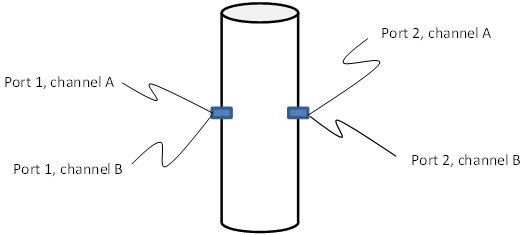
On J-2X, wherever we have a critical measurement (meaning that it is a parameter that can control engine operation, including redline shutdown) we have a quad-redundant architecture. In the sketch below, I attempt to illustrate what that actually means.
Thus, we have two actual measurement ports and each port has two independent sets of associated electronics. We are doubly redundant in order to ensure reliability. However, does a man with two watches ever really know what time it is? No, he doesn’t because he cannot independently validate either one. We have a similar situation, but in our case we simply want to make sure that none of the measurement outputs that we are putting into our decision algorithms are completely wacky. So we do channel-to-channel checks and we do port-to-port checks to make sure, at the very least, some level of reasonable consistency. Thus, we cannot know the exact answer in terms of the parameter being measured, but we can decide if one of the measurement devices themselves is functioning improperly. This process is called sensor qualification. On test A2J027, our sensor qualification scheme told us that one port was measuring something significantly different than the other port, different enough that something was probably wrong with at least one of the sensors. That resulted in disqualifying the measurements from one of the two ports. In flight we would have kept going unless or until the remaining port measurements notified us of a true problem, but on the ground, as I discussed, we are more conservative.
When we investigated the apparent issue, what we discovered was that we should have predicted the port-to-port offset. It turns out that due to the engine conditions that we’d dialed up for that particular test, we were running the gas generator at a mixture ratio higher than we’d yet run on the engine. When we went back and examined some component testing that we’d done with the workhorse gas generator couple of years ago, that data suggested that yes indeed, when we head towards higher mixture ratio conditions, our two measurements tend to deviate. This suggests, perhaps, a greater amount of localized “streaking” in the flow at these conditions. Localized effects like this are not uncommon in gas generators or preburners. Because of the particular configuration of the J-2X, with more mixing available downstream of the measurements, the impact due to such variations on the turbine blades is minimized. This too was shown in the component level testing. Thus, the sensors were fine and the engine was fine. It was just out qualification logic that needed reexamination. Sometimes, this is how we learn things.
So that tells you all about those handful of cases where we didn’t quite get what we intended. Overall, however, the engine E10002 test campaign was truly a rousing success. Here are some of the key objectives that were fulfilled:
- Conducted 13 engine starts – 10 to primary mode, 3 to secondary mode – including examinations of interface extremes for a number of these starts.
- Accumulated 5,201 seconds of hot-fire operation.
- Performed six tests of 550 seconds duration or greater.
- Conducted eight “bomb” tests to examine the engine for combustion stability characteristics. All tests showed stable operation.
- Characterized nozzle extension thermal environments.
- Characterized “higher-order cavitation” in the oxidizer turbopump.
- Demonstrated gimbal operation (multiple movement patterns, velocities, accelerations) with no issues identified.
Hot on the heels of the success of engine E10002, we have engine E10003 assembled and ready to go. I love this picture below. This is the engine assembly area. We have three engine assembly bays and, on this one special occasion, we happened to have each bay filled. Engine E10001 is all of the way on the left. It is undergoing systematic disassembly and inspection in support of our design verification activities. Engine E10002 had just come back from its successful testing adventure. And engine E10003 is all bundled up and ready to travel out to the stands to begin his adventure. [I’m not sure why this is the case, but E10003 has a male persona in my mind so the possessive pronoun “his” seems to fit best.]
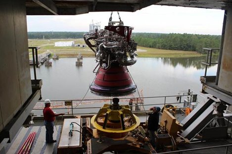
 In the picture below you see E10003 being brought into the stand on A2. Note the water of the canals in the background. See the concrete pilings over to the left in the background. Those are where the docks are for the propellant barges that we discussed above.
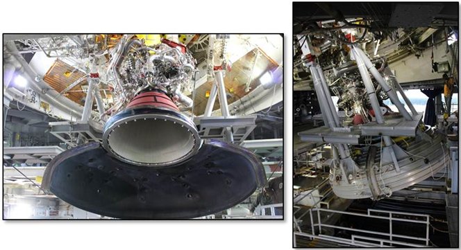
 In the pictures below, you can see E10003 installed into the test position. The picture on the left shows half of the clamshell brought down into place. Compare this picture to the sketch at the beginning of this article. The picture on the right shows what the engine looks like with both halves of the clamshell brought down into position.
 So that’s where we stand. Engine E10003 has begun testing in November 2013 and continue on into 2014. As always, I will let you know how things are going and if anything special pops up, you can be sure that we’ll discuss it here at length. After all, there’s not a whole lot that’s more fun than talking about rocket engines.


