J-2X Progress: Engine Assembly, Volume 4


It’s been about three weeks since I last reported on the progress of J-2X Engine 10001 assembly.  What I would like to do is show you pictures of great big additions to the engine, but the truth is that for the last few weeks the engineers and technicians have been diligently plugging away at smaller stuff, at the details.

“It’s the little details that are vital. Little things make big things happen.” – John Wooden

I would hazard to guess that Coach Wooden was talking about basketball – or maybe life in general – when he spoke these words, but on a rocket engine, everything has to work so the details of the big stuff and of the little stuff are equally vital. 

So, here are some pictures and some details…


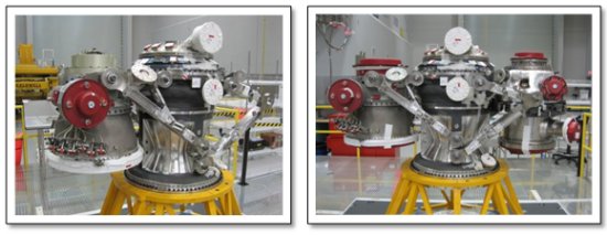
We’ll start with a picture of the overall assembly and the addition of the item in the dashed, red oval on the right-hand side of the picture.  That is the gas generator.  Yep, that little thing powers both turbopumps and therefore is the driving force behind the whole engine.  Here is a closer picture.
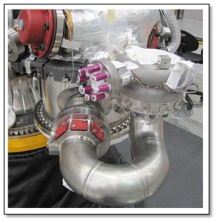

As I’ve mentioned before, during the whole assembly process, things either have covers attached or are wrapped in tape and other protective media so that no debris gets in the engine and so that delicate parts are not damaged.  You can see that here on the gas generator.

Note that in the image of the gas generator above, you will see the “U-duct” from an earlier blog series entry regarding Direct Metal Laser Sintering.  This, right here on the engine, is the piece for which we may have found a future innovative manufacturing method.

Next is a picture of a mounting plate.  This is not even a primary piece of the engine if you were looking at a schematic, but it’s a vital piece nonetheless.  On this mounting panel sits the two Main Injector Exciter Units (MIEUs).  An MIEU is analogous to the ignition coil in your automobile engine but with a good bit more punch.  We use two units for redundancy to further ensure overall reliability.  If, in the morning, your ignition coil goes dead in your station wagon, well you’re just stuck in your driveway.  However, if during a launch mission you can’t get the J-2X started, then you’re stuck somewhere over the Atlantic Ocean at two or three hundred thousand feet.  That’s a somewhat more treacherous situation.  So we use very highly reliable parts and we use two parallel units.
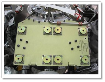

What makes this mounting plate interesting is that it has vibration isolators so that the noise and shaking of the engine don’t impact the electrical components of the units.  Those eight circles on the mounting plate are the tops of the isolators so there are four for each unit.  Kinda cool little details.

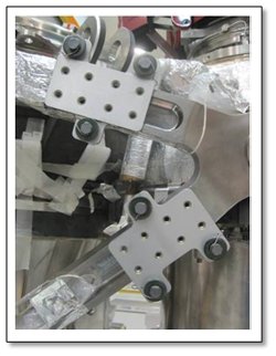
Next, more mounts.  In the picture below, you will see two rectangular items, each with eight holes.  These are mounts on which will eventually reside pressure transducers.  There are several such transducer mounts across the engine.  These particular mounts are installed on the arms that hold the oxidizer turbopump.  So, we have mounts installed on mounts and you can begin to understand the complex layering that an engine assembly represents.

One strategy that is used quite often during the assembly process is to do stuff unattached from the main assembly itself.  Over on a separate bench, you put together a bunch of smaller pieces and then take this whole subassembly over to the engine for installation.  Over the past couple of weeks, this is exactly what has been done with the ancillary line “raceway.”  Below is the completed raceway subassembly. 
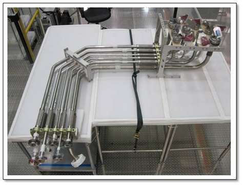

All of the lines and brackets and nuts and bolts were separate pieces when the engineers and technicians began. 
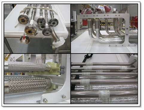

Each line in that assembly is different since each line represents different fluids coming to or coming from the engine at different pressures and temperatures.  There is helium, oxygen, hydrogen, and even nitrogen.  There are pressures over 3,000 psi and less than 50 psi.  There are temperatures approaching the boiling point of water and those less than 400 degrees below zero Fahrenheit.  Thus, some of these lines shrink from the cold.  Some of them stiffen with high pressure.  Yet all of them have to be flexible to accommodate the gimballing of the engine and every one of them is vital either to the engine or to the vehicle.  In other words, it is a complex design, a complex manufacturing process, and a complex subassembly to put together.  And it all has to be correct.  Details, details, details!

Lastly, I’d like to toss in a cool picture from the test stand.  Below is a picture from test stand A-2, with the engine mass simulator installed.  This is where J-2X Engine 10001 will be tested.  The brightly painted, yellow hunk of metal is supposed to weigh the same as a J-2X and have the same dimensions.  It’s used for checkouts of various systems including the test stand.
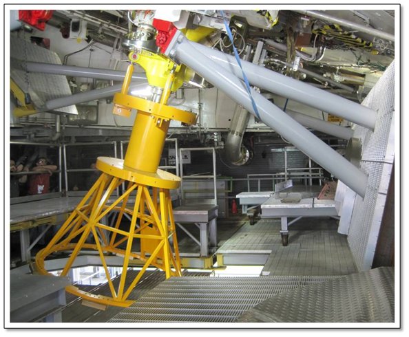


Another thing of note in that picture from A-2 is large gray object to the right.  That is half of a water-spray system that will be used during testing when no nozzle extension is installed on the engine.  Near the top of the picture is a hinge painted bright red.  When deployed, the gray water-spray structure will have been swung down so that its two pieces (the one shown and the other one to the left and out of the picture) join at the bottom of the engine nozzle.  This is all part of the system to deal with the substantial, combustible, fast moving, and very hot exhaust from the engine during test.  This water-spray system was installed specifically for J-2X testing.

That’s where we stand.  The details of the engine assembly are coming together, with more parts arriving at the NASA Stennis Space Center every day, and with the test stand is being readied to accept installation of the engine.  This is Volume 4 of the assembly saga.  By the time Volume 5 is ready for the blog, we should be very close to having a fully assembled engine.  Wahoo!


J-2X Progress: Engine Assembly Continues


J-2X Progress: Engine Assembly Continues

Once upon a time, I used to consider myself reasonably handy with a saw and a drill and a miter box and various rudimentary woodworking tools.  I certainly knew my limits, so I never did anything too complex, but most of the fun from pursuing such projects was the creativity involved.  I didn’t plan out a great deal.  I preferred an evolving, organic (i.e., lazy) approach.  Given the nature of the forgiving materials involved, that was generally fine.  In my wife’s art studio, there’s a cat tree with six or seven beds that fills an entire wall.  I built it with no drawings, kind of on the fly, and it still turned out okay (or, at least, the cats seem to think so).


That is not, however, how you assemble a rocket engine.  You don’t wing it.  You plan everything.  The materials are not forgiving.  Just about everything is heavy and, if you drop it, or scratch it, or scuff it, or nick it, then you have the joyful experience of traipsing through a paperwork exercise to make sure that whatever you damaged is still usable.  In other words, rocket engine pieces are both extremely rugged and rigid yet also precisely machined and fragile.  Oh, and unlike two-by-fours, rocket engine parts aren’t cheap and as easily replaced as a trip down the street to Home Depot.  Thus, a great deal of time spent poring through the planning documentation and lifting and moving things with exceptional care.


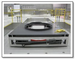
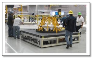
You can think of a rocket engine as a large, three-dimensional jigsaw puzzle.  The pieces have to fit together exactly and properly.  To make this happen, you first have to have really well-manufactured parts, but then you also need good ground support equipment (GSE) and knowledgeable, competent, and dedicated technicians.  Below is a picture of one critical piece of GSE, the engine build dolly.  This is essentially a rolling piece of elevated floor onto which you build in the engine.  Considering with the engine sitting on it, plus tooling, plus the technicians themselves doing the work that the dolly could be holding well over 6,000 pounds, this is a stout piece of equipment.


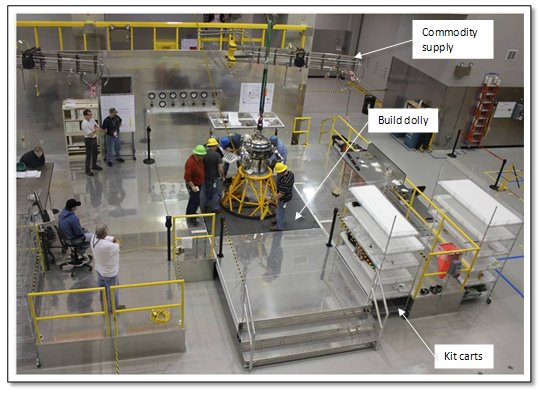
When I built the big cat tree, I just moved around the mess in my garage and I pulled my pickup out of the driveway to lay out the bigger pieces.  The picture below is the J-2X assembly area.  Note that there aren’t any flower pots with last year’s dead petunias, or half-empty bags of bird seed, or cast-off, half-used rolls of duct tape scattered about the floor.  In other words, it doesn’t look like my garage.  It is extremely clean and orderly.  It is a FOD-free zone:  FOD = foreign object debris.  When assembling an engine, you do not want ANYTHING in the engine that does not belong there.  I will be showing you pictures below of various stages of engine assembly so far and you will notice that there is tape and/or plastic closures over every open hole where something might accidentally fall.  One dropped nut or hunk of wire or wad of tape and you’re either forced into a costly disassembly exercise to get the stuff out or, worst case should the FOD be missed and left in the engine, you could have an engine failure in test and the loss of tens of millions of dollars of hardware. 


The other thing that you will notice from the picture of the assembly area is how well the whole thing fits together.  Pieces of the floor retract to allow for the dolly to be positioned in the middle.  The kit carts have bays into which they can slide for convenient access to the necessary hardware.  There is an overhead boom with commodities available for when the assembly and checkout processes require gasses or electrical power or a hookup to a simulated vehicle stage computer.  And, of course, just above the boundary of the picture is an overhead crane for lifting operations. 

Now, can you just imagine the magnitude and glory of my cat tree if my garage was so neat, well organized, and fully equipped?  Difficult to fathom, huh?

So, where does the engine assembly stand?  Since I last reported the initiation of assembly, great strides have been made.  Let’s step through the biggest pieces of the sequence.  First, the birdcage was put into place on the build dolly.  Remember, the yellow birdcage is a simulator for the first portion of the nozzle.  Later, it will be replaced with the real nozzle.  The dolly was then wheeled into place in the assembly area. 


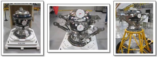
Below is the next sequence.  The picture farthest on the left is the MCE, i.e., the main combustion element (composed of the main injector attached to the main combustion chamber) sitting in its shipping box.  In the middle is a picture of the MCE with the turbopump arms installed.  From these four heavy arms will be hung the fuel turbopump and the oxidizer turbopump.  And, on the right, is a picture of this the whole assembly of MCE with the turbopump arms mounted on top of the birdcage.


Next, the two turbopumps were installed, first the oxidizer turbopump and then the fuel turbopump.  I can state that here quite simply in a single sentence, but go back to that series of pictures above: planning, lifting, moving, positioning, etc.  A great deal of careful work went into each step.


Now, I don’t know about you, but this is getting darn exciting for me.  If I squint hard at that last picture and add some ducts in my mind, then that really looks a whole lot like an honest to goodness rocket engine.  J-2X is coming together!  In another month or so, it will be fully assembled and early this summer we will be demonstrating the first new, human-rated NASA rocket engine since 1975 (…yes, 1975, think: the fall of Saigon, Patty Hearst still on the lam, the Thrilla in Manilla – Ali v. Frazier III, Tiger Woods and Kate Winslet born, sentences being handed down for Watergate, the very first episode of Saturday Night Live, and me as the star kickball player during fifth grade recess…). 

Two final notes for this article.  First, I would like to thank Brian West for all of the engine assembly pictures and background information for these pictures.  Keep up the great work!  Second, I would like to thank my cat Kesey for his starring role in the center of the cat tree picture.  Being that round and that lazy takes years of dedicated practice.

J-2X Progress: Valves, Commands into Action

Everyone seems to like analogies between the composition of a rocket engine and that of the human body.  These are often colorful but not always helpful.  In some cases, however, they work pretty well.

Okay, so let’s start with your body as it is.  Now, imagine removing all of your bones.  Guess what?  You’re an immobile lump.  Even if your brain is sending signals and your muscles are contracting, you’re not really moving anywhere.

This time, let’s instead start with your body as it is, but now imagine removing all of the muscles and tendons that connect the muscles to the bone.  You’ve got a central nervous system and you’ve got bones, but with nothing to flex, the chain is broken and you’re stuck where you sit (assuming that you can still actually sit).

And, of course, if you instead start with your whole self and imagine removing your brain and/or your central nervous system that connects your brain to your muscles, again, you’ve achieved perfect immobility (i.e., you look like me on Saturday afternoons during college football season).

The point is that in order for you to be up and about, shoveling snow, doing laundry, playing pool, typing, whatever, you need both the command center that figures out what signals to send — your brain — and you need things that turn those signals into action — your muscles and tendons and bones.  In a rocket engine, the analogue for the brain is the engine controller.  It is a computer that receives instructions from the vehicle and sends out commands to the engine pieces so as to fulfill those instructions.  The analogue for the muscles are the valve actuation systems.  These are the things that “flex” and cause movement.  And the analogue for the bones, the final effectors that make things happen, are the valves.

The controller sends out signals and then the actuation system responds by shuttling pressurized working fluid — helium for J-2X though some engines use hydraulic fluid instead — where it needs to go so that the valves move and the engine comes to life.  The engine goes from being a lump of inert, shiny metal to a “living” beast of flowing propellants, spinning turbomachinery, lots of fire, and thundering, rumbling thrust.

On the J-2X, there are 42 valves.  Most of this number is made up of small valves like check valves, solenoid valves, and valves in small lines like the bleed lines.  There are also a handful of big valves — the primary valves — that directly control the flow of propellant and, in one case, combustion products along the plumbing of the engine.  Each of these primary valves is connected to a valve actuator, i.e., the muscle.  These valve actuators convert the energy of high pressure helium gas into mechanical rotation of the valve.  This is accomplished by pressurizing cavities and moving pistons and, in this way, the valve is pushed opened or closed.  I’ve used this schematic shown below before, but it is useful here as well since it illustrates the primary J-2X valves: Main Fuel Valve (MFV), Main Oxidizer Valve (MOV), Gas Generator Fuel Valve (GGFV), Gas Generator Oxidizer Valve (GGOV), and the Oxidizer Turbine Bypass Valve (OTBV).

The control logic for J-2X is relatively simple.  The whole subject of different kinds of control logic is a good topic for a future article, but suffice it to say that for normal operation the J-2X: starts on command, can change between two power levels on command, and shuts down on command.  The control system is designed to do other things as well, including monitoring the health of the engine, but these operations are the commanded functions.  Start and shutdown can be simplistically thought of as: the valves open and the valves close.  It’s a bit more complicated since the timing of opening and closing is extremely important, but the open/close notion is basically true.  The oddball action is the one consisting of changing power levels.  That is accomplished by controlling the power to the oxidizer turbine via the OTBV.  This bypass valve effectively allows for limited, independent control of the two turbopumps.  By altering the power to the oxidizer turbopump (OTP), you can control the engine thrust level (and, simultaneously, mixture ratio).

The OTBV for J-2X is designed and built by Pratt & Whitney Rocketdyne (PWR), the prime contractor for the whole engine.  In addition to being responsible for the “oddball action” on the engine of changing power levels, it represents a challenging design due to the range of operating conditions.  Unlike the other primary valves on the engine that see, essentially, one narrow range of environmental conditions, the OTBV has to function in temperatures approaching 420 degrees below zero Fahrenheit (liquid hydrogen conditions) immediately prior to start and then, suddenly, within 1 second of ignition of the gas generator, see temperatures approaching 750 degrees above zero Fahrenheit (combustion products).  That broad range of operating conditions requires special design considerations and special materials.  Not only do you have to worry about wear and tear under such harsh conditions, but you also have to think about simple operation under the extremes of thermal expansion.

The original, Apollo-era J-2 engine also had an OTBV, but it was used slightly differently and was designed much differently.  It was a butterfly valve whereas the J-2X OTBV is a ball valve. 

No, the valves shown in the picture are NOT rocket engine valves.  I can’t show any internal workings of rocket engine valves.  In fact, I am not even allowed to describe the general design details that make the J-2X OTBV kind of unique.  However, the basic elements of rocket engine valve functionality for butterfly and ball valves are essentially the same as these water valves.  The biggest difference is the replacement of the handles with pneumatically driven actuators.  Back during the Apollo era it would seem that butterfly valves were most frequently used, but after many years of usage on the Space Shuttle Main Engine, ball valves are often preferred these days.  They generally require less torque to move and they generate better flow characteristics and flow rate control capability.

The first OTBV unit for use on the upcoming development engine testing for J-2X is in the later phases of manufacturing at the PWR in Los Angeles.  All of the individual piece parts are schedule to be complete by the beginning of February and assembly will begin the middle of February.  The valve then will be integrated the actuator and shipped to the NASA Stennis Space Center to be put on the first engine.