A couple of articles back, I asked the following question:
“The whole orange-flame thing is not something I entirely understand…Any ideas from anyone else?”
I was talking about the flame stack during a night test at the NASA Stennis Space Center. It was a legitimate question. Combustion chemistry is really not my specialty. Lots of things are not my specialty. Try as I might, I’ve found that I can’t know everything about everything. Indeed, considering the many brilliant and knowledgeable people with whom I have the privilege of working here at NASA, I’ve come to accept the conclusion that there is a lot more stuff to know than can ever be learned. But that can never stop you from learning something new. And so I have with this.
In response to my blog question, we received a number of comments on the blog and those are posted. Thank you for your inputs and interest.
However, behind the scenes (so to speak), a coworker of mine, Robin Osborne, who does have experience with this kind of stuff read the blog and starting poking around amongst her notes and amongst her fellow experts in the field of flame spectroscopy. Below is a picture taken of igniter testing at MSFC using a gaseous hydrogen-oxygen mixture. Here too you can see a red-orange flame although it takes a distance for that colored portion to show itself.
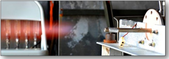
According to Dr. Robert Pitz from Vanderbilt University, “Pure hydrogen (with no sodium) — air flames will glow red in a dark room due to the water vapor emission lines.” Both Dr. Joseph Wehrmeyer working in support of the Air Force and Richard Eskridge from NASA concur, noting that water vapor generates an orange-red-infrared continuum in such flames. However, all of these individuals also noted that there is a strong orange coloration in such flames due to sodium contamination within the hydrogen. The sodium is present as sodium hydride within the liquid hydrogen which decomposes at high temperatures to generate the vibrant color. The sodium contamination is a byproduct of how large, industrial quantities of hydrogen are made for uses such as, for example, flying the Space Shuttle. Dr. Christopher Dobbin of NASA noted that in the 1990 timeframe he was engaged in an analysis of the flame plumes ejecting from the Space Shuttle Main Engines (SSME). He said, “The (time) average sodium concentration we measured in the SSME exit plane was 0.091 parts per billion.” That doesn’t sound like much, and it’s not enough to impact engine performance or operation, but it’s still enough to measure based upon spectral analysis of the plume. Another possible contaminant, according to Richard Eskridge, is potassium and that can further contribute red emissions.
So, there you go. It’s a matter of water vapor at the right temperature and pressure (and therefore density) and a couple of key contaminants in the fuel. It’s “common knowledge” around here amongst us Datadogs that the plume of a Lox/Hydrogen rocket engine is clear. But that’s not entirely correct. It’s nearly clear. It still has the characteristic red-orange tint, but it’s at a density where the emission is too low to see. On the other hand, for the flame stacks at the test facility — the origin of this whole discussion — we’re talking combustion at atmospheric pressure so the water vapor products are denser as are the relative contamination levels since it’s a fuel-rich environment. And that’s why they show up at those brilliant colors in the nighttime pictures.
See, even old Datadogs can learn new tricks. Thank you to everyone who added their two cents, but especially to Robin Osborne for her inputs and insight.
3 exists for helping 2
3 is progression asdendently vertical
2 is basic orizontal where union is
Looking at the original picture, aren’t those sodium-vapor lights in and around the test stand? If so, sometimes the answer is right in front of you…. 😉
I found this site to be helpful:
student dot fizika dot org/~nnctc/spectra.htm
while not an element, it has water vapor spectra at the bottom. So the bit of red can come from H and H2O. The bright yellow from Na double lines.
Thanks for the followup. Good luck with future tests of J-2X!
Mark – That is an excellent observation! The colors from the test stand lights do appear to match the color of the flame, and Bill has verified that sodium discharge lamps are used in the Stennis light fixtures. It is a convenient coincidence, but as it turns out, the test stand lights provide a visual reference point to support the theory that the majority of the flame luminosity is from sodium contamination in the liquid hydrogen supply.
NASA’s website just recently posted a story about the F-1 rocket engine that powered the first stage of the Saturn rocket. Apparently, it is the biggest “single nozzle, liquid fueld” rocket engine ever!
Because i’ve been reading this blog, getting excited about the J-2X, I’ve been able to understand some of the terminology used in the story and the complexities. Things like the thrust chamber, gas generator and the various turbopumps were used in the story and because you gave us so much information about these things, it made the story that much easier to understand and grasp. Thank you so much for taking the time to explain these things in laymen’s terms for us “regular folk”.
I was wondering if you wouldn’t mind providing some comments about the F-1 engine yourself. I would guess you have some unique perspective and insight on this marvelous engine. And, although they are two different engines for two different purposes, maybe just a little commentary on engine comparison between the J-2X and the F-1.
Thanks again for all your wonderful posts and good luck with the J-2X!!
@Bruce:
Thank you for your kind words regarding this blog, but it’s truly my pleasure to be able to share this stuff. It’s one of my favorite parts of my job.
Regarding the F-1, yes, I know about the press release. I had the opportunity to review that little write-up before it went out. It was in response to the news stories regarding the proposed efforts by Mr. Bezos (of Amazon.com fame) to dredge up some Apollo Program Saturn V engines from the bottom of the ocean. That could be a cool adventure and I hope that he’s successful. Those engines are definitely a piece of our national history.
In terms of similarity to the J-2X, both the F-1 and the J-2X are gas generator cycle engines. And, of course, both the F-1 and the J-2X predecessor, the J-2, flew on the Saturn V vehicle that first took humans to the Moon. And both engines are/were developed by the Rocketdyne company. Back in the time of the Apollo Program it was North American Rocketdyne. Today it is Pratt & Whitney Rocketdyne (and in between it’s been Rockwell Rocketdyne and Boeing Rocketdyne … such is the corporate history of many aerospace companies over the last fifty years). Beyond these similarities, however, these are two very different engines.
First off, the F-1 uses kerosene as the fuel rather than liquid hydrogen. Sometimes in the literature you’ll see reference to “RP-1” as the fuel (which creatively stands for “rocket propellant one”), but that’s simply a designation for purified, high-grade kerosene. Second of all, the F-1 is a hoss. Whereas the J-2X comes in at a thrust level of less than 300,000 pounds-force, the F-1 comes in at 1,500,000 pound-force of thrust. And a follow-on upgrade effort conducted during the Apollo era developed a version of the engine called the F-1A that put out somewhere around 1,800,000 pound-force of thrust. Some of that incredible “oomph” comes just from using a dense propellant like kerosene as opposed to hydrogen, but the F-1 is also simply a darn big engine. I recently had the opportunity to see and handle some internal pieces of an F-1 and I guess that it’s kind of like handling the bones of a brontosaurus. You recognize what you’ve got in your hands as a bone, but you can’t imagine the size of the beast from which it came.
Another difference between the F-1 and the J-2X is the use of a single turbopump. When you use hydrogen for a propellant, you need to pump it differently than you do your oxidizer. You require pump speeds roughly three times faster for liquid hydrogen as compared to liquid oxygen. However, kerosene is close enough in density to liquid oxygen that you can use similar speeds. This than gives you the opportunity, should you choose to take it, of building one giant turbopump that does the job of pumping both propellants. On the J-2X, we have a fuel turbopump that has a turbine end and a pump end and we have an oxidizer turbopump that has its own turbine end and pump end. That’s pretty typical (though not universal) for Lox/hydrogen engines. In the F-1, you have one turbopump that has one big turbine, one section dedicated to pumping fuel, and one more section dedicated to pumping oxygen. All three of these elements (turbine, pump, pump) are contained on a single spinning shaft.
The original J-2 has a tube-wall main combustion chamber and nozzle. I believe that way back in an earlier blog article I talked about means for cooling combustion chamber walls and back in the 1960’s, tube wall was the only way to go. So, the F-1 also then had a tube-wall combustion chamber and nozzle design. The J-2X, however, leverages the experience of the Space Shuttle Main Engine and the RS-68 engine and uses a channel-wall combustion chamber. Now, should anyone ever get in their head to reconstitute the F-1 (or F-1A) design, it’s probably likely that they’d resort to a channel-wall combustion chamber design as well rather than try to go back and recreate the tube-wall. That’s just the way that we do things these days. It’s a bit heavier, but there are numerous manufacturing and operational advantages.
And, speaking of reconstituting F-1 … I am going to carefully tiptoe around the treacherous realm of space politics. The discussion about this has been going on as long as I’ve been associated with NASA. My officemate in graduate school did his Master’s Thesis specifically about the historical F-1 combustion instability efforts that that thesis was in response to folks down here at NASA MSFC. When I first started working in this field in 1990, there was a study underway regarding the restart of the F-1A production line as an asset to feed the development of whatever was to follow the Space Shuttle. That effort produced an extensive report and then, promptly, faded away. Ten years (or so) later, we were again asking the question of what comes next and proposals were once again made to bring back the F-1. This time the proposals didn’t get too far and faded quickly as NASA took a different direction with regards to engine development and studies. And, finally, just recently as we were once again faced with the question of “what’s next?” the topic of reconstituting the F-1 (or F-1A) has come up. We’ll see what happens. I can tell you, though, that I could walk down the hallways here at NASA and quickly collect a group of engineers willing to give their eye-teeth for the opportunity to jump on that project should it ever come to pass. It’s almost the utopian dream job for any rocket-guy/gal and is often wistfully discussed in such terms.
It is important to note that while we’ve talked about bringing back the F-1 for, well, at least a quarter century, we have entirely abdicated the role of building very large kerosene rocket engines. The development of the F-1 was originally begun as an Air Force activity in the 1950’s, but was taken over by NASA when the Air Force decided that it didn’t fit in their plans. For many, many years, they used the RS-27 engine on the Delta II and Delta III launch vehicles but those launches have stopped and RS-27 production has stopped. The previous versions of the Atlas vehicle used the MA-5 engine, but that too has fallen by the wayside. Today, on the Atlas launch vehicle, the Air Force uses an RD-180 kerosene rocket engine that puts out just under 1,000,000 pounds-force thrust. That is a Russian rocket engine. There is also, out there being promoted and proposed for various uses is the NK-33 rocket engine that puts out just under 350,000 pound-force of thrust. That too is a Russian engine. On the American side the only relatively large kerosene rocket engine activity that I know of is the Merlin engine developed by the SpaceX company. According to what I can find on the web, that engine comes in somewhere around 140,000 pounds-force of thrust.
So, that’s a lot of blather on the topic of the F-1, how it compares to the J-2X, and other related issues. I hope that you find it interesting or useful.
I thoroughly enjoyed reading your comments. Thank you so much!
Even though the F-1 or F-1A might not be revived, I assume they are going to need a mighty big first stage rocket at the height of the SLS program to boost the huge payloads up into the upper atmosphere (I think I read that they may have payloads as big as 135 tons!).
Hopefully, those that enjoy working on those big rocket engines will get the opportunity to do so.
I really like the J-2X the more I read your posts about it. One of the things I really find amazing is that you can re-start the engine in space.
Thanks for this explanation. Since we’re talking about colors in exhaust plumes… I was always wondering about this blue “cone” in the exhaust of the SSMEs. Could this also be an emission line? and why does it appear at that specific location behind the nozzle?
@ Christian: The blue “cone” downstream of the SSME nozzle exit is part of the shock diamond that is formed as supersonic, hot exhaust gases are expelled from the SSME. The shock diamond, consisting of oblique and normal shock waves, is generated as a result of the supersonic exhaust flow being over-expanded (lower than atmospheric pressure) as it exits the nozzle.
You can think of the exhaust gas as being “squeezed” by the surrounding atmospheric gas. As the exhaust gas is squeezed, oblique (angled) shock waves are formed on the outer boundary of the exhaust flow, turning the flow inward toward the centerline of the nozzle. This increases the pressure and decreases the exhaust velocity, until the flow turns parallel to the nozzle centerline. When this happens, a normal shock wave (also known as a Mach disk) forms, immediately slowing the flow to a subsonic speed.
The pressure of the exhaust gas downstream of the Mach disk is now higher than atmospheric pressure, causing the exhaust gas to expand outward. Oblique shock waves are again formed on the outer boundary of the flow, but this time they are allowing the exhaust flow to turn outward, away from the nozzle centerline. This decreases the exhaust pressure and increases its velocity, which means the exhaust flow, once again, is squeezed by the surrounding atmospheric gas. In other words, the process described at the beginning repeats itself, setting up a series of Mach disks. But with each repetition the process weakens, until the exhaust pressure finally equalizes with the ambient pressure.
The cone you asked about is where the first, largest, and brightest Mach disk forms just downstream of the SSME nozzle. The Mach disk forms the base of the cone. It’s exact location is a function of the diameter of the nozzle exit, the pressure at the nozzle exit, and the ambient pressure.
You also asked about the blue color (I’d actually call it whitish-blue) and you were curious if it came from an emission line. After discussing it with some of my more experienced colleagues, we have concluded that the visible luminosity in the shock diamond can probably be attributed to at least four different sources: 1) water vapor emission from burning of excess hydrogen with air on the outer interface of the shock diamond (note that the temperatures are extremely hot in these regions, well over the hydrogen-air auto-ignition limit), 2) optical emission from the excitation of rotational, vibrational, and electronic modes of molecules in both the internal and external regions of the shock diamond. Single atomic species may also emit light due to electronic excitation, 3) hydroxyl recombination radiation, and 4) plasma radiation resulting from the weak ionization of the sodium and potassium contaminants that we know are present with the H2.
To my knowledge, the sources of the luminosity in the SSME shock diamond have not been extensively researched, so much of this is speculative, but it’s based on the experience of people who have studied these types of exhaust plumes.