LEO Progress: J-2X to Test Stand A1

“Nothing behind me, everything ahead of me, as is ever so on the road.”
– Jack Kerouac, On the Road

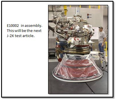
Recently, J-2X development engine 10002 was on the road.  If you remember, E10002 went through a six-test series on test stand A2 that began in February and finished up in April.  The next planned phase of E10002 testing is on test stand A1.  In between these series, the engine was back in the assembly area of NASA Stennis Space Center Building 9101.

1038170

This respite between test series allowed for a complete series of inspections of the engine hardware.  This is vital piece of the learning process for engine development.  The basic truth is that a rocket engine is just darn tough on itself when it fires.  The reason that we test and test and test is to make sure that our design can stand up to the recurring brutal conditions.  The chance to look for the effects of that testing through detailed inspections away from the test stand is an opportunity to collect a great deal of useful information.

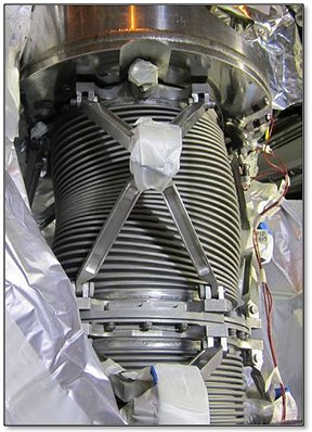
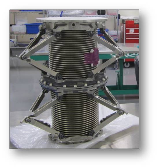
Also, even before the engine arrived at the assembly area, the stub nozzle extension was removed.  This was done while the engine was still installed in the test stand.  Remember, the testing on test stand A2 was performed with a passive diffuser and so we were able to use an instrumented stub nozzle extension to examine the nozzle thermal environments.  On A1, there will be no diffuser.  We’ll be firing straight into the ambient Mississippi afternoon and so we’ll not have any nozzle extension attached.  The other change made to the engine — this one made while in the assembly area — was that we swapped out the flexible inlet ducts so that we can use our specially instrumented ducts for the gimbal testing on A1.  These ducts will provide a great deal of unique data when we gimbal the engine and force the inlet ducts to twist and bend and they are designed to do.

Below is my favorite picture from the recent assembly activities for E10002 back in Building 9101.

1038171

“FOE” stands for “foreign object elimination.”  I love this picture because it is a demonstration of how dedicated and meticulous are our assembly techs and how much basic integrity they bring to their job every single day.  In the rocket engine business we tend to be fanatics about foreign objects (i.e., random debris of unknown origin) hanging around.  The reason for this is that if you spend enough time in the business, you will eventually have a story of what happens when trash gets into the engine.  The rocket in question might be an amazingly powerful beast pumping out five hundred pounds of propellant per second generating 300,000 pounds of thrust, but all it takes is one bit of junk in the wrong place to destroy the whole thing in fractions of a second.

In the picture above is a small nut that was found in the periphery of the assembly area.  Shoot, if this was my garage you’d be lucky to find a clean patch not strewn with various bits of stuff like nuts, bolts, wads of duct tape, old hunks of sandpaper, that lost pair of pliers, a “Huey Lewis and the News” cassette, or, well, who knows what.  But the rocket engine assembly area is NOT my garage (thank goodness).  When something is found like a stray nut in the picture above, that sets off an investigation.  Where did it come from?  How did it get loose?  What procedure allowed this nut to escape control?  This is serious stuff.  Yet, just think about how easy it would have been for a tech to see that stray nut, pick it up, and stick it in his pocket.  They could have avoided the whole minor investigation thing entirely.  But that’s not what they did and that is not what they do.  Because they know that if they do not show the necessary integrity and methodical approach to continue to learn and perfect our procedures, then the next stray nut could be lodged where it could do terrible damage.

Here are the techs moving E10002 out of its assembly bay and unpacking it for transport.

1038172

And a couple more pictures of the process in Building 9101.

1038173

Here’s the engine ready for the road, then being lifted up the side of the test stand, and then sitting in the porch area while sitting on the engine vertical installer.  I really enjoy the pictures of the engine trucking about sunny NASA SSC.  That picture was the inspiration for including the Jack Kerouac quote at the beginning of the article.  It’s bright and shiny and full of so much thrill and promise.

1038174

All of this should look reasonably familiar.  It is the process that we follow, more or less, whenever we take an engine out to the stand.  Getting the engine into and out of A1 is a bit easier since you don’t have to deal with moving the diffuser out of the way, but they’re really quite similar.  The slightly different flavor that we’ve got for this testing is the addition of the thrust vector control system.  In the picture below you can see where these hang.  The engine mounts up with the gimbal bearing to the stout, yellow thrust take-out structure.

1038175

The two hydraulic actuators are also attached to the thrust take-out structure but slightly outboard and at 90 degrees apart.  These actuators are what will swing the engine around as if we were steering a vehicle.  Here, below, is another, closer view of the thrust take-out structure and the actuators.

1038176

In the picture below, E10002 is mounted up to the thrust take-out structure.  The gimbal bearing is the shiny object towards which the arrow is pointing.  If you look over to the right side of the picture, you can see one of the “scissors ducts,” i.e., the flexible propellant inlet ducts.

1038177

The next picture shows one of the hydraulic actuators hooked up to the engine.  As you can see the tolerances are awfully tight.  That’s an important vehicle integration consideration.  If this was a vehicle stage rather than a test stand to which we were attaching the engine, the thrust structure and the actuators would be the responsibility of the stage manufacturer.  Making sure that the stage and the engine can work together in such close quarters takes a great deal of vigilance between the two teams.

1038178

So, you’re probably asking yourself, to what do these actuators connect on the engine?  That’s a very good question.  It certainly isn’t obvious from the assembly pictures.  The actuators connect to the forward manifold of the main combustion chamber (MCC).  Below is a computer model of the MCC with the two actuator attachment points shown.

1038179

The MCC is really the heart of the whole engine, the sturdy framework stuck right in the middle, so it makes sense that when you want to push the engine around, this is what you’d have to push.  This final picture below of the engine completely mounted into the stand.  Again, it’s amazing to think about that whole thing being able to move about and not having one component run into another component or the actuators or the stand.  It is quite the integration miracle.

1038180

Testing for E10002 on test stand A1 will commence in June.  So, if all goes well, for the next J-2X update, I’ll be able to link in a video of the engine firing and twisting about.

BTW, NASA is in the process of swapping software used for posting blog articles and comments and such.  As part of this process, they have to shut down the capability to accept input comments for a short time, specifically the first two weeks of July 2013.  Sorry about that.  But after that, it ought to be up and running as normal.

J-2X Progress: Current Status, The End of 2012

Once upon a time, not that long ago, people used to communicate by what were known as “letters.”  These were written documents.  Yes, actual hardcopy, paper items. And they were often transcribed by hand or, sometimes, generated on what was known as a “typewriter,” which was basically a manual, analog printer with no I/O port beyond direct keypad entry.  These “letters” were sent to their intended recipients using a small denomination currency with an adhesive backing that is recognized for exchange by only one quasi-governmental agency. 


I know that some of you may have doubts that people communicated with each other in primitive ways prior to email and text messages, but witness the cultural clues from the 1961 song illustrated above. 

It was always believed that the toughest letter to receive was the dreaded “Dear John” letter (as in, “Dear John, I’ve fallen in love with someone else…”).   However, I think t’at the hardest letter to write is the “it’s been awhile” letter.  This one starts, “Well, it’s been awhile since I’ve written.  Sorry.”  This blog article is just like one of those letters.  It’s been awhile since I’ve written one of these articles and I’m sorry about that.  I could give you a big long list of all the really, really serious stuff that I’ve been doing instead, but that’s just a bunch of feeble excuses so I’ll keep them to myself.  Instead, I’ll just get down to business and give you a status report on the J-2X development effort.

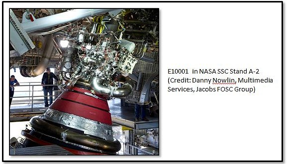
Engine #1 (E10001) Testing is Complete!
Over fourteen months and across the span of twenty-one tests, more than 2,700 seconds of engine run time was accumulated and recorded, including nearly 1,700 seconds of hot fire with an instrumented nozzle extension.  With this engine we achieved stable 100% power level operation by the fourth test and full mission duration by the eighth test.  While we don’t have any official statistics on the issue, most folks around here believe that we accomplished those milestones faster than has ever been done on a newly developed engine.  We learned how to calibrate the engine and the sensitivities that the engine has to different calibration settings, i.e., orifice sizes and valve positions.  We were able to estimate performance parameters for the full-configuration of the engine at vacuum conditions and the calculations suggest strongly that all requirements are met by this design and met with substantial margin.  This is significant considering that we’ve long considered our performance goals to be pretty aggressive.  Well, our little-engine-that-could showed us that it did just fine with those goals, thank you very much.

One of the truly unique and successful aspects of the E10001 testing was the testing of a nozzle extension.  This component is a key feature that allows J-2X performance to far exceed that of the J-2 engine from the Apollo Program era.  While it is true that we cannot test the full-length nozzle extension without a test stand that actively simulates altitude conditions, we did test a highly instrumented “stub” version that allowed us to characterize the thermal environments to which the nozzle is exposed during engine hot fire and it demonstrated the effectiveness and durability of the emissivity coating that was used.  This stub-nozzle configuration is actually the current baseline for the in-development Space Launch System vehicle upper stage.

Another key success for E10001 was the demonstration of both primary and secondary power levels with starts and shutdowns from each power level and with smooth in-run transitions back and forth between them.  That smoothness was thanks, in part, to demonstrating our understanding of the control of the engine.  From the very first test it was clear that we understood pretty well how to control the engine in terms of proper control orifices for the various operating conditions.  What we did not entirely understand — in other words the fine-tuning details — we successfully learned via trial-and-error throughout the E10001 test series.  All of this learning has been fed back into further anchoring our analytical tools and models so that we can move forward with J-2X development with a great deal of confidence.

Okay, so that’s a brief description of just some of the good stuff.  We had lots and lots of good stuff with the E10001 testing, far more than just that I’ve discussed here (see previous blog articles).  The somewhat unfortunate part was the way in which the E10001 test series came to an end.  On test A2J021, we had a disconnection between the intent for test and the detailed planning that led to the actual hardware configuration we ran for the test.  That disconnection led to an ill-fated situation.  Let me explain…

The J-2X gas generator has ports into which solid propellant igniters are installed.  These igniters are like really high-powered Estes® rocket motors that light off when supplied with a high-energy electrical pulse.  The flame from the igniter lights the fire of the hydrogen-oxygen mixture during the engine start sequence.  It’s essentially the kindling for the fire of mainstage operation.  The igniters perform this function at a very specific time during this sequence.  If you try to light the fire too early, then you may not have enough propellant available in a combustible mixture so you get a sputtering fire.  If you try to light too late, then you may have too much propellant built up such that rather than getting a good fire, you get an explosion instead.  But here’s a key fact: You have to plug them in or they don’t work.

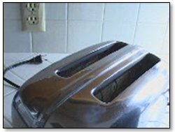
Have you ever stuck bread in the toaster, pushed down the plunger, gone off to make the coffee, and come back only to find that your darn toaster is broken?  You curse a little because you’re already late for work and this is the last darn thing you need.  You would think that somebody somewhere could make a toaster that lasts more than six months or a year or whatever.  For goodness sake!  We put a man on the moon and yet we can’t … oh, wait … um … ooops, it’s not plugged in.  My bad.

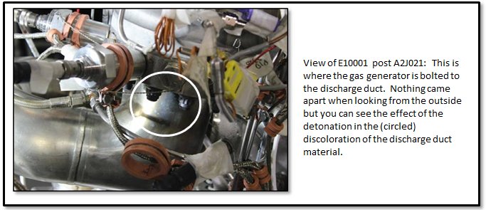
In a nutshell, that’s what happened on test A2J021.  The electronic ignition system sent the necessary pulse, but because of the uniqueness of our testing configuration as opposed to our flight configuration the wires carrying the pulse weren’t hooked up to the little solid propellant igniters in the gas generator.  In the picture below you can see the external indication that something was not entirely good immediately after the test.  The internal damage was more extensive to both the gas generator and the fuel turbopump turbine.

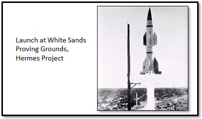
Many years ago, I met an elderly engineer who was still on the job well into his 80’s because he loved his work.  His entire career had been dedicated to testing.  He’d actually been there, out in the desert, in the 1940’s testing our very earliest rockets as part of the Hermes Project.  One day, they had a mini disaster on the launch pad.  He told me that the rocket basically just blew up where it sat.  Boom and then a mess.  And, it was his job to assemble the test report.  Being a conscientious, ambitious, young engineer, he recorded the facts and offered a narrative abstract and extensive, annotated introduction that categorized the test as, well, a failure.  Not long after submitting his report, one of the senior German engineers in the camp came into his office, put the test report down on the desk, and said that the tone of the report was entirely wrong.  He said, “Every test report should begin with: ‘This test was a success because…'”  The purpose of testing is to gather data and learn.  If you learn something, then your test was, by definition, a success on some level.  I’ve tried very hard to remember this very important bit of wisdom.

So, A2J021 was a success because we learned that we had some deficiencies in our pre-test checkout procedures.  It was a success because it was an extraordinary stress test on the gas generator system.  No, it didn’t recover and function properly, but neither did the engine come apart.  While that might seem like a minor detail, when you’re hundred miles from the surface of the earth, you would much rather have a situation where an abort is possible than a failure that could result in collateral vehicle damage and make safe abort impossible.  We have a stout design.  Good.  Also, this test failure was due to a unique ground test configuration.  In flight, it’s not really plausible just because we would never fly in this configuration.

So, E10001 completed its test program with a bang.  Kinda, sorta literally.  But it was nearly the end of its design life anyway, so we didn’t lose too many test opportunities, and, as I said, even with test A2J021 the way it happened we learned a great deal.  Overall, the E10001 test series was an outrageous success.  Rocketdyne, the J-2X contractor, ought to be darn proud and so should the outstanding assembly and test crews at the NASA Stennis Space Center and our data analysts here at the NASA Marshall Space Flight Center.  Bravo guys!  Go J-2X!

Power-Pack Assembly 2 (PPA-2) Testing is Complete!
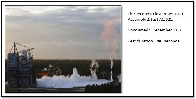
Over ten months and across the span of thirteen tests, nearly 6,200 seconds of engine run time was accumulated and recorded on the J-2X Power Pack Assembly 2.  That’s over 100 minutes of hot fire.  Three of the tests were over 20 minutes long (plus one that clocked in at 19 minutes) and these represent the longest tests ever conducted at the NASA Stennis Space Center A-complex.  But more than just length, it was the extraordinary complexity of the test profiles that truly sets the PPA-2 testing apart.

Because PPA-2 was not a full engine with the constraints imposed by the need to feed a stable main combustion chamber, and because we used electro-mechanical actuators on the engine-side valves and hydraulic actuators on the facility side valves, we could push the PPA-2 turbomachinery across broad ranges of operating conditions.  These ranges represented extremes in boundary conditions and extremes in engine conditions and performance.  On several occasions we intentionally searched out conditions that would result in a test cut just so that we could better understand our margins.  As the saying goes: It’s only when you go too far do you truly learn just how far you can go.  We successfully (and safely) applied that adage several times.  In short, we gathered enough information to keep the turbomachinery and rotordynamics folks blissfully buried in data for months and months to come. 

On an interesting and instructive side note, the PPA-2 testing also showed us that we needed to redesign a seal internal to the hydrogen turbopump.  In the oxygen turbopump, you have an actively purged seal between the turbine side and the pump side.  After all, during operation you have hydrogen-rich hot gas pushing through the turbine side and liquid oxygen going through the pump side.  You obviously don’t want them to mix or the result could be catastrophic.  That’s why we have a purged seal.  But for the hydrogen turbopump you don’t have such an issue.  During operation, at worst should the two sides mix you could get some leakage of hydrogen from the pump side into the turbine side that is already hydrogen rich.  In order to maintain machine efficiency, you don’t want too much leakage, but a little is not catastrophic (and can be used constructively to cool the bearings).  What could be dangerous at the vehicle level, however, is if you have too much hydrogen floating around prior to liftoff.  This is especially true for an upper-stage engine like J-2X that’s typically sitting within an enclosed space until stage separation during the mission.  You could have the engine sitting on the pad for hours chilling down and filling the cryogenic systems and you don’t want gobs and gobs of hydrogen leaking through the turbopump since any leakage ends up within the closed vehicle compartment housing the engine.  That’s just asking for an explosion and a bad day.

To avoid this, within the J-2X hydrogen turbopump we have what is called a lift-off seal.  And, as the name applies, it’s a seal that actively lifts off when we’re ready to run the engine.  When the engine is just sitting there chilling down, not running, with liquid hydrogen filling the pump end of the hydrogen turbopump, the seal is, well, sealed.  Then, when we’re ready to go, it unseals and allows the turbopump to operate nominally.

During the PPA-2 test series we found that we formed a small material failure within the actuation pieces for our lift-off seal.  Then, upon analysis of the test data and a reassessment of the design, we figured out what was most likely the cause and Rocketdyne proposed a redesign to mitigate the issue.  Again, going back to that important piece of wisdom: This testing was a success because, in part, we learned that we needed a slight redesign of the lift-off seal.  That’s the whole purpose of development testing!  Everything always looks great when it’s just in blueprints.  It’s not until you hit the test stand do you truly learn what’s good and what need to be reconsidered.  In the end, this sort of rigor and perseverance is what gives you a final product that you feel good about putting in a vehicle carrying humans in space.  And that, truly, is what it’s all about.

As with E10001, the PPA-2 test series was simply an outrageous success.  Rocketdyne should be proud and so should the outstanding assembly and test crews at the NASA Stennis Space Center and the data analysts at the NASA Marshall Space Flight Center.  Bravo guys!  Go J-2X!

Engine #2 (E10002) Assembly is Underway
Our next star on the horizon is J-2X development Engine 10002.  It is being assembled right now, as I’m typing this article.  It is slated for assembly completion in January 2013 and it will be making lots of noise and very hot steam in the test stand soon after that.  While our current plans are to first test E10002 in test stand A2, we will later be moving it to test stand A1.  This, then, will be the first engine then to see both test stands.  The more important reason for the A1 testing, however, is because that will give us the opportunity to hook up some big hydraulic actuators and gimbal the engine, i.e., make it rock and tilt as though it were being used to steer a vehicle.  Now that will be some exciting video to post to the blog!  I can’t wait.

 
Happy New Year!
So, this has been my “it’s been awhile” letter.  Hopefully this will bring everyone up to speed with where we stand with J-2X development.  In my next article, I will share with you some of what’s been keeping me from my J-2X article writing over the last several months.  And, hopefully, it won’t be several months in the making.  So, farewell for now and Happy New Year!  On to 2013 and another great year full of J-2X successes.  Go J-2X!

J-2X Extra: What's in a Name?

It’s been over six years since I started working on the J-2X development effort.  I missed the very first day that the notion of a J-2X engine was conceived, but I was only two weeks late to the party.  So, I’ve been with the thing almost from the beginning.  And throughout that entire period, whenever I get the chance to talk to people outside of our small, internal rocket engine community (…for very understandable reasons, they don’t let us out much), the single, most frequent, recurring, and ubiquitous question that I hear is something along the lines of this:

“How come you guys are spending so much time and effort recreating an engine that flew nearly fifty years ago?”

That is an entirely fair question.  I am not a volunteer.  As generous and as charitable as I like to consider myself, I do accept a paycheck.  So do my coworkers.  So does our contractor.  Thus, all this work to develop J-2X isn’t free and, as I said, the question asked is therefore a valid point of discussion.

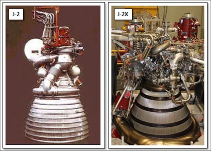
To a certain degree, I tried to answer this question by way of analogy in a J-2X Development Blog article posted a year and a half ago (December 2010) about a 1937 Ford Pickup truck.  But analogies and metaphors can sometimes be abstruse.  Let us eschew obfuscation and arrive expeditiously to the point:  What makes J-2X different from J-2?

The J-2 rocket engine, developed by Rocketdyne and the NASA Marshall Space Flight Center, was qualified for flight in 1966.  Between August 1966 and January 1970, 152 engines were produced.  Between 1962 and 1971, some 3,000 engine tests were conducted.  The J-2 engines were used for the second stage of the Saturn 1B vehicle and the second and third stages of the Saturn V vehicle.  (Note that I wasn’t much involved in the original J-2 project considering that it was concluding just as I was figuring out that whole reading thing in First Grade.  Remember Dick and Jane, Sally and Spot?)

The most significant differences between these two engines can be found in their performance requirements.  I suggest that these are most significant because it is these differences that lead directly to a majority of the physical design differences between these two engines.

That’s an increase in thrust level of over 25%.  And the specific impulse increase is on the order of 6%.  While that doesn’t sound like much, in the realm of rocket engines, given that the J-2 and the J-2X are using the same power cycle, it’s huge.  It means that we’re pulling staged-combustion or expander cycle levels of performance from a gas generator engine.  That’s really something special.

From requirements flows form.  Or, as stated by architect Louis Sullivan (mentor to Frank Lloyd Wright): “Form follows function.”  You don’t design and build a rocket engine a certain way because it’s neato.  It’s designed to meet requirements that fulfill mission objectives.  It’s not like a 1959 Cadillac where stuff was added just because it looked really cool (picture below courtesy of the Antique Automobile Club of America Museum in Hershey, PA).

In order to get that kind of boost in performance for J-2X, we had to do two fundamental things:  (1) move more propellant mass through the engine, and (2) use that propellant more efficiently.  To the first point, J-2X pumps into itself and expels out approximately 20% more propellant per second than did J-2.  That translates into needing a whole lot more pumping power.  Here’s a comparison of power requirements for the J-2 and J-2X pumps (as a point of reference, a typical NASCAR engine generates about 750 horsepower):

That’s between 80% and 90% more power for J-2X as compared to J-2.  The reason that you need so much more is not only the need for greater flow, but also the need for more efficiency in usage is manifested as higher discharge pressures.  I’ll explain this further below.  But first, let’s talk about the hydrogen pump just because it’s an interesting story.

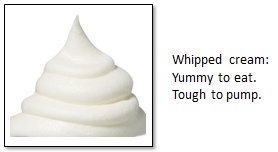
Back in the day, when J-2 was first being conceived of, the technology of how exactly to pump liquid hydrogen was still being developed.  The RL10 engine existed already, but it was about 1/10th the size of J-2.  Some work had been done with pumping hydrogen as part of the NERVA nuclear thermal propulsion development effort, but not everything learned there was widely distributed.  This relative lack of information resulted in J-2 having a liquid hydrogen pump that was, in reality, an axial compressor.  You see, the problem is that liquid hydrogen is so light that it kinda sorta acts as much like a gas as a liquid.  I’ve heard it described as being like whipped cream but less sticky. 

So, do you pump it like a liquid or like a gas?  You typically use axial compressors for gases.  That’s what you use in turbojets for airplanes.  And you can get it to work with liquid hydrogen, as J-2 clearly demonstrated, but it’s not the best solution.  One of the issues is that a compressor has some unfortunate stall characteristics where the effectiveness of the pump can plummet during the start transient.  This is caused by what is known as the start oscillation that always happens in liquid hydrogen engines.  Picture this:  Prior to start, everything up to the valves that hold back the flow on the hydrogen side is chilled down to liquid temperatures (typically 36 to 39 degrees Fahrenheit above absolute zero).  Then the valves open during start sequence and the liquid hydrogen suddenly comes into contact with relatively warm downstream metal.  The result is similar to what happens if you sprinkle water into a hot frying pan.  In other words, the liquid boils immediately upon contact.  In a rocket engine this causes a transient “blockage” as this voluminous plug of newly formed hydrogen gas gets pushed through the system.  In terms of the pump, this sudden “plug” downstream results in a transient, elevated pressure at the pump discharge and this can cause the pump to stall, especially if it’s an axial compressor.  In order to overcome this effect, they had to precede the J-2 start sequence with several seconds of dumping of liquid hydrogen through the whole system to pre-chill the metal downstream of the valves. 

Okay, so that’s not too much of a big deal, but it was a nuisance.  By the end of the 1960’s, it was clear to most folks that the better way to pump liquid hydrogen was to use a centrifugal pump and that’s the way we’ve done it ever since (including on the J-2S engine, which was an experimental engine tested in the early 1970s as a follow-on to J-2).  With a centrifugal pumps, you get to avoid the stall issues inherent with an axial compressor and you get a more compact, powerful machine.  Which is good considering how much more power we need to pull out of the pump for J-2X.

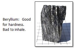
In addition to changing from axial to centrifugal, we had to make a number of other changes to the turbomachinery.  In one place, we used to use on J-2 an Aluminum-Beryllium alloy.  Well, you can’t use Beryllium anymore since it is considered too dangerous for the machinists working with the metal on the shop floor.  In particular, Beryllium dust is toxic.  And since we really like the guys working on the shop floor (as well as following the law), we had to go to another alloy.  Also, we redesigned internal seal packages and rotor bearing supports using the most modern analysis and design tools and methods.  In short, there’s not much in the turbomachinery, both fuel and oxidizer, that wasn’t reconsidered and redesigned to meet the imposed requirements.

Now, the other reason that we need 80% to 90% in addition to pumping 20% more “stuff,” is the fact that we had to get that stuff to higher pressures.  Why?  As discussed in a recent previous blog article, if we go to a higher combustion chamber pressure, then we can have a smaller throat and, with a smaller throat, we can have a larger expansion ratio without getting too out of hand with engine size.  And, because of our extreme specific impulse requirement (remember: form follows function), we need that very large expansion ratio.  So here are the top-level thrust chamber parameters:

The J-2 main combustion chamber was built from an array of tubes braze-welded together.  When you needed the walls of that chamber to be actively cooled, this was the most common way to make combustion chambers “back in the day.”  This is a fine method of construction, but it is kind of limited in terms of how much pressure it can contain.  For the Space Shuttle Main Engine project in the early 1970’s, we needed the capability to handle a much higher chamber pressure and so we (i.e., Rocketdyne working in coordination with NASA) developed what is called a “channel-wall” construction method.  So, to get the higher performance using the higher chamber pressure, we had to abandon the tube-wall construction method for the J-2X main combustion chamber and use a channel-wall main combustion chamber similar to the Space Shuttle Main Engine.

The main combustion chamber is on the top end of the scheme to get the larger expansion ratio.  On the bottom end, we had to add a large nozzle extension.  On the J-2, the nozzle consisted of another tube-wall construction.  For J-2X, we have a tube-wall section that is actively cooled and then we have the radiation-cooled nozzle extension beyond that.  The reason for transitioning is because the nozzle going out to a 92:1 expansion ratio has a diameter of nearly 10 feet and a tube-wall construction that large would be unreasonable heavy.  In other words, from the vehicle perspective, the engine would be so heavy that its weight would offset any benefit from performance.  The radiation-cooled nozzle extension is significantly lighter.

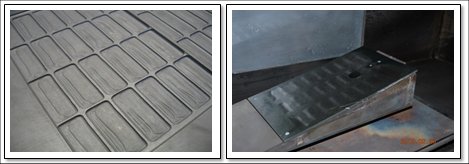
That make it sound easy, doesn’t it?  If you want more performance, just strap on a big hunk of sheet metal and call it a nozzle extension.  I wish that it were that easy.  First, you need to figure out what material to use.  Metal?  Or maybe carbon composite?  Plusses and minuses for both.  Then you need to learn how to fabricate the thing light enough to be useful.  And then you have to make it tough enough to survive the structural and thermal operating environments.  In the pictures immediately above you can see a sample panel of how the J-2X nozzle extension is made and you can also see one of these samples sitting in a test facility where we blasted the panel with high velocity hot gases to partially simulate nozzle flow environments.  The panel has a coating that enhances the radiation cooling so not only does the panel itself have to survive the environment, but so does the special coating.

Other things that we’re doing to get more performance out of the engine include the use of a higher density main injector and the use of supersonic injection of the turbine exhaust gases into the nozzle.  When you talk about “injector density,” what you’re talking about is the number of individual injectors stuffed into a given space.  Up to a point, the more injectors that you have, the better mixing you get, and, from that, the better performance you an extract from the combustion process.  The picture below shows some testing that was done early on in the J-2X development effort to optimize the main injector density.

With regards to the turbine exhaust gas, on J-2 it was effectively dumped into the nozzle with the only intent being to not mess up the primary flow.  For J-2X, we carefully designed the exhaust manifold and internal flow paths to get as even a distribution as possible around the nozzle and, from there, we are injecting it into the flow through mini throats at supersonic velocity.  Here again we are extracting as much performance as we can given the simplicity of the power cycle.

The next element of the engine to consider is the thing that creates the power that drives the turbines…that spins the pumps…that feeds the injectors…that fill the chamber…that makes thrust.  In other words, I’m talking about the gas generator.

So, due to the increased power needs of the pumps, the gas generator has to flow twice as much propellant and at higher pressures through the turbines as compared to J-2.  The temperatures are pretty much the same since this parameter is mostly limited by material properties of the spinning turbine components.  In terms of “form following function” from a design and development perspective, these increased power requirements translated to the fact that gas generator used for J-2 was entirely inappropriate for J-2X.  It just wouldn’t work.  Rocketdyne had to design a new gas generator based upon work that they had done as part of the development of the RS-68 rocket engine (used on the Delta IV vehicle).  In the past, I’ve shown some pictures and even video of the whole development test series that we conducted to validate the design of our gas generator.  Below is a representative picture of our gas generator component test bed. 

Something not captured in the table of performance requirements way up above is the bevy of requirements imposed on the J-2X in terms of health monitoring and controls functionality.  These too resulted in differences between J-2 and J-2X. 

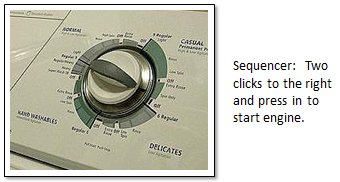
The J-2 engine had a sequencer to control the engine.  Yes, it consisted of solid-state electronics, but other than that it was pretty much like the timer on your washing machine.  The J-2X has an engine controller, which is a computer with embedded firmware and software that allows for a great deal of functionality in terms of engine control and system diagnostics.  Some of these diagnostics we call redlines.  These are specific limits that we place of measured parameters such that, should we break the limit, then we know that something bad has happened to the engine.  The idea is to catch something bad before it turns into something potentially catastrophic.  This is all part of the higher reliability and safety standards that have been applied to J-2X as compared to J-2.

The J-2X controller is composed of two independent channels such that if one fails, the other can take over.  For critical measurements that inform the controller during engine operation, we actually take four separate measurements, compare them to make sure that they’re reasonable and good, and then use algorithms to perform the health checks.  That’s one result of the imposition of more detailed requirements pertaining to reliability and safety.  Along these same lines, we also have a number of design, construction, and workmanship standards that were applied to every aspect of the J-2X engine design, development, and fabrication.  These standards, in combination with more evolved and advanced analysis tools, have, in a number of cases, further driven design changes away from heritage J-2 designs to what we’d call modern human-rated spaceflight hardware.

In an old J-2 manual, I found reference to a reliability value for that engine equivalent to 2,000 failures per one million missions.  The requirement for J-2X is 800 failures per one million missions and, of those, only 200 can be “uncontained failures” meaning that the engine comes apart and potentially threatens other vehicle elements.  So, all over the engine system we’re pushing more propellants, operating at higher pressures, generating more thrust, and squeezing out more performance efficiency, and we have to do this in a manner that results in an engine that has over twice as reliable as the heritage design.  The result is an engine that is bigger and heavier than its historical antecedent:

So, in summary, here are the components that we had to change to meet J-2X requirements:
• Turbomachinery
• Main injector
• Main combustion chamber
• Nozzle
• Gas generator
• Added a nozzle extension
• Swapped the sequencer with a controller

What does that leave?  Valves?  Nope.  Because of the higher flowrates and pressures, we had to drop the heritage designs for the valves and go to a design more akin to the Space Shuttle Main Engine.  Ducts?  Nope.  Once you’ve changed all of these other things, you end up rearranging the connecting plumbing just as a matter of course.  Even the flexible inlet ducts were changed slightly to accommodate more stringent design standards. 

Form follows function; function flows from requirements; requirements flow from mission objectives.  Different mission, different requirements, different function, and a different result.  Thus, the J-2 and the J-2X share a name and share a heritage — in many ways the J-2 (and the J-2S) was the point of departure for the J-2X design — but the J-2X is truly its own engine.  Lesson learned: Don’t assume too much from a name.


J-2X Progress: Once Upon a Time at Stennis…

I enjoy movies.  I don’t get to watch much television due to other endeavors that consume much of my time, but if I do it’ll almost always be one of four things on the screen:  some news program, a sporting event, a history program, or a movie.  And I like lots of different kinds of movies.  Some of my favorites include: The Hustler, Singing in the Rain, Rocky, Schindler’s List, Barfly, Hannah and Her Sisters, Fargo, The Apartment, The Godfather, Leaving Las Vegas, The Deer Hunter, Hoosiers, Nobody’s Fool (the Paul Newman one).  I don’t believe that one could decipher a pattern from that list other than the fact they all follow the classic narrative structure:

Think of the classic “stranger comes to town” story.  (1) It’s a quiet little town and all is peaceful.  (2) Then a stranger comes to town and stirs up all kinds of trouble.  (3a) In the end, the stranger marries and settles down with the prom queen and everyone learns to live with one another.  Or, (3b) in the end, the stranger ends up mysteriously dead and lying in the gutter along the road leading out of town and they secretly bury him promising never to mention it to anyone from out of town.  Or, (3c) in the end, the stranger ends up mayor of the town by exposing and driving out the secretly corrupt sheriff.  Obviously, the possibilities are endless and that’s why there are thousands and thousands of stories to be told.  But the root of all of this is the middle block, “…something disturbs that situation and troubles ensue…”  Nobody ever tells an interesting story where nothing happens.  And with no “troubles” of some sort, nobody cares about the resolution.

So, that brings me to rocket engine testing and the fact that it is always interesting.  This article is intended to bring you up to date on the status of our J-2X test campaign at the NASA Stennis Space Center in southern Mississippi.  Remember, we last left our heroes on test stand A1 with PowerPack-2…

Test A1J015, J-2X PowerPack-2: It ran 340 seconds of a planned 655 seconds duration.  The test profile called for simulated primary mode and secondary mode (i.e., throttled) operation.  Also, throughout the test, turbomachinery speed sweeps were planned meaning that we systematically varied turbine power, increasing and decreasing, to force the pumps through a broad range of conditions.  It was during one of these sweeps that the fuel turbopump crossed a minimum speed redline and the test was cut short.  Before the test, we knew that it would be close and the analytical prediction was just enough off from reality to cause the early cut.  Nevertheless, most of the primary objectives were achieved and the test was a success. 

One of the things that we often talk about when discussing an engine test is the “test profile” or sometimes the “thrust profile.”  The test/thrust profile is the plan for what you’re going to do during the test.  When we say that we had a planned duration of 655 seconds, that value comes from the test profile that is agreed upon prior to the test.  Usually a test/thrust profile is a single page showing engine power levels and propellant inlet conditions, but for these complex PPA-2 tests, the test profile can be expanded to include such things as these turbomachinery speed sweeps.  To give you an idea of what an engine test/thrust profile looks like, here is one for a Space Shuttle Main Engine (SSME) test performed back in 2001.  It contains a wealth of knowledge about the test to be run.

Test A1J016, J-2X PowerPack-2:  It ran 32 seconds of a planned 1,130 seconds duration.  In this case, unlike the previous test, because we cut so early we can’t really say that it was mostly a success.  However, every time that you chill an engine, successfully get it started, and shut it down safely, you have accomplished something significant and you are always collecting data and learning.  The early cut in this case had nothing to do with the PowerPack-2 performance.  Rather, it was a facility issue, a hydrogen fire due to a leak.  As I’ve said before, the PowerPack-2 is an oddball test article in that it is half engine and half facility.  That makes the interfaces technically difficult in some cases due to thermal and structural loads.  The leak and fire in this case was on the facility side near one of these difficult interfaces. 

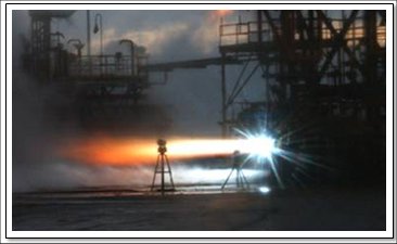
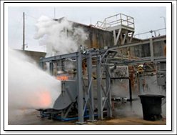
Below is a picture captured off a video taken during the test and behind the structure and the piping you can see the bright orange flame that resulted in the early cut.  This issue of hydrogen leaks and fires has been somewhat recurring so a team of NASA and contractor folks stepped forward to work towards a resolution of the issue.

Test A1J017, J-2X PowerPack-2:  It ran the full, planned 1,150 seconds duration.  That’s over 19 minutes of continuous rocket engine operation and that’s pretty amazing.  It was the longest, most complex engine test ever conducted across the long history of the NASA Stennis Space Center A Complex.  We did some wacky stuff on test stand A1 during the XRS-2200 (linear aerospike engine) development effort and there were a couple of longer SSME tests in the B Complex twenty-some years ago, but test A1J017 stands out for the combination of complexity and duration.  The test profile contained over a dozen unique, steady state “set points,” i.e., prearranged combinations of engine operational conditions and facility boundary conditions.  The objectives of this test included speed sweeps for the oxidizer turbopump and an examination of cavitation performance for both the oxidizer pump and the fuel pump.  Pulling off this test was a dazzling success with many people deserving credit.

So, trouble ensues (hydrogen fire on test #16) and the combined team of NASA Stennis, NASA Marshall, test operations and support contractors, and Rocketdyne worked through to a resolution of the issue and a new situation of unprecedented success has been achieved.  It’s easy to write a blog like this when reality lines up so conveniently in the narrative form. 

But back at the ranch, our heroes find J-2X development engine E10001 on test stand A2…

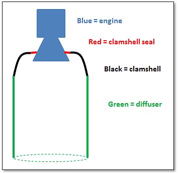
To refresh your memory, we’d last tested E10001 on stand A2 back in December of last year.  Back then, we were testing the engine without a nozzle extension and not using the passive diffuser system on the stand.  This year, we were going to get back to testing E10001 but now with a nozzle extension so that necessitated use of the passive diffuser.  The Stennis folks installed a clamshell and seal apparatus that connects the engine to the diffuser thereby allowing the diffuser to “suck down” to pressures lower than sea level ambient.  In my crude sketch below, I try to show you how this fits together.

A key piece in this arrangement is the clamshell seal.  Whereas the engine is obviously metal and the clamshell and diffuser and big pieces of structural metal, the clamshell seal is a fibrous/rubber-ish piece that has to provide the seal that allows the whole thing to work together and simulate altitude operation when the engine is running.  It has to be strong yet compliant so as to accommodate movements of the nozzle during hot fire.  To give you an idea of how strong it needs to be, let’s calculate the force imposed on the seal during operation.  Ambient sea level pressure is 14.7 psia (pounds per square inch, absolute).  Let’s say that in the diffuser, during operation, it will be about 10 psi lower than sea level ambient.  In reality, the pressure will be slightly lower than that, but 10 is a nice round number to work with.  Let’s further say that the diameter of the nozzle at which the seal is attached is about five feet (or, 60 inches).  That’s pretty close to reality, give or take a bit.  And, let’s say that the seal itself is about six inches in width.  So, the total area of the seal is:

So, if the pressure differential across the seal is 10 pounds per square inch and you have 1,244 square inches of surface area, then that makes for over 12,000 pounds of force — or more than 6 tons!  Wow, so that seal and the brackets that holds it in place still needs to be pretty darn tough.

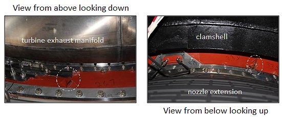
Test A2J011, J-2X E10001: It ran 3 seconds of a planned 7 seconds duration.  The early cut was due to a facility redline violation; specifically, the measured pressure within the clamshell did not drop down the way that it was supposed to.  Post-test inspections quickly revealed why this redline violation occurred.  The clamshell seal was torn up.  If the seal doesn’t seal, then the pressure differential is not maintained and so, appropriately, we tripped a redline.

An informal team was assembled of NASA, contractor, and Rocketdyne folks and the design deficiency was quickly identified.  New parts were designed and fabricated and, in a matter of just a couple of weeks, we were once again ready for test.

Test A2J012, J-2X E10001:  It ran the full, planned 7 seconds duration.  The objectives for this test were to demonstrate that the clamshell, seal, and diffuser arrangement was properly working and to perform a bomb test in the main chamber.  The testing arrangement worked perfectly and the bomb test did not reveal any combustion stability issues. 

Test A2J013, J-2X E10001:  It ran the full, planned 40 seconds duration.  This was yet another bomb test and again there was no combustion stability issue uncovered.  The neato thing on this test was that while the engine started to primary mode operation (i.e., 100% throttle), it switched to secondary mode operation (i.e., throttled) mid-test.  This was the first operation of the complete J-2X engine (as opposed to just the powerpack portions) in secondary mode. 

Test A2J014, J-2X E10001:  It ran the full, planned 260 seconds duration.  This test represented several more “firsts” for J-2X.  This was the first time that the J-2X was started directly to secondary mode.  It was the first time that the J-2X switched, in run, from secondary mode to primary mode.  This was the first J-2X test with a stub nozzle extension that offered the opportunity to perform an in-run calibration of the facility flow meters and, in so doing, provide for a good estimation of engine performance.  It turns out that E10001 is, to our best understanding, exceeding expectations in terms of required performance.

Again, the old narrative structure holds:  New guy comes to town (the stub nozzle extension).  The situation changes (new test stand configuration to accommodate the stub).  Troubles ensue (the clamshell seal gets torn up).  Resolution is found (new design for clamshell seal attachments).  And a new situation is achieved (we’re knocking off successful test after successful test). 

But, there is a twist (literally) to our denouement.  I’ll explain this twist by starting with a picture:

Can you see it?  This is a picture of the fuel inlet duct.  Remember, this duct has an inner and an outer shell (or bellows as we call them) so that in between there will be vacuum to keep the hydrogen cold, like a Thermos® bottle.  Between tests, one of the customary inspection techniques used to ensure that you’re good to go for the next test is to do a series of helium leak checks.  You systematically pressurize different portions of the engine and make sure that everything is still sealed up tight.  Well, when they pressurized this portion of E10001, they got what we’re calling “squirm.”  If you look closely at the duct you’ll see that on the left-hand side the convolutions are bunched together and on the right-hand side they’re spread apart.  This indicated that there was leak in the inner bellows of the duct so that the cavity between the two bellows was pressurizing with the leak-check helium.  The squirm effect was due to the outer shell was deforming — squirming — due to that pressurization of the vacuum cavity. 

Now, there are several important things to note about this.  First, this particular duct is a heritage piece of hardware.  It was not made for E10001.  It was made during the Apollo era for J-2 and J-2S, forty years ago.  It had seen its fair share of hot-fire history long before it reached E10001.  Second, the new ducts being built for J-2X have a design modification that ought to mitigate this kind of failure.  Third, we can see in the test data, with perfect hindsight, exactly when the leak occurred in test A2J014 and the engine ran for some time with the leak and nothing catastrophic happened.  Thus, while nobody is happy when something breaks, in this case there’s no need for overreaction.

Getting back to the narrative structure and this little twist at the end, I kind of think of this like a teaser — a cliff-hanger — that leads to a sequel.  Will our intrepid heroes dig their way out of this situation?  Will the test program recover and move ahead to new successes and glory?  Or will the monster creep up from the dark, dank Pearl River swamps and terrorize the test crew…?

…oops, wrong movie. 

[Hint:  We’ll be fine.  Already moving out at full speed.  In the immortal words of Journey (i.e., Jonathan Cain, Steve Perry, and Neal Schon) “Oh the movie never ends. It goes on and on and on and on…”]


J-2X Extra: Human-Rated Chili

I enjoy cooking.  Most people think that when I say that, it’s because I’m an engineer by training, that I like cooking for the structured notion of a recipe and exactly measuring things out and the chemical precision of mixing that with this, at this speed, under these conditions, with these implements, and then forming it all together with a specified heat input over a given time using appropriately sized and shaped pots and pans optimized for uniform heat transfer, blah, blah, blah, blah…

But, that’s way, way off from the truth. 

Actually, I like to cook things that allow for, let’s say, “significant organic creativity.”  I make a mean vegetarian chili, but you can be sure that it will be different every single time that I make it since it’s always from memory and my memory ain’t what it used to be.  I wing it.  And that’s fun.  And even though it’s fun and even though the details vary slightly, it’s been good every time (so far).  The worst side effect that I could attribute about any particular version might be a bit of heartburn (properly mellowing and blending habanero peppers is an imprecise art form I have not yet consistently mastered).

So, what does my free-form chili cooking this have to do with J-2X?  Believe it or not, I want to talk about one of the adjectives that we frequently apply to the J-2X engine: “human-rated.”  What does that mean?  We use that term (or the older, less politically-correct formerly used term “man-rated”) all of the time and, for the most part, those of us within our little clique understand the general context of its meaning.  But if you asked any of us to explain, you’d likely get a wide variety of different, complex, and mostly correct yet often partial answers.  I am no genius and, despite all odds, I will do my best to provide a reasonably complete framework for a definition so as to help you better understand the J-2X engine. 

And, it will come back to my cooking analogy.  Really.
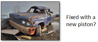
First, we need to recognize that there is really no such thing as a “human-rated rocket engine.”  That is shorthand terminology that ought to be written out as: “a rocket engine that could be suitable as part of an overall, human-rated launch system.”  Think of it this way:  Let’s say that you had a total junker of a car but you installed one perfectly pristine, top-quality piston.  Do you now have a good car or do you still have a junker?  You’d still have a junker, of course.  Or, let’s say that you had a really nice car but all of the spark plugs were corroded, eroded, and barely functional.  Do you still have a nice car?  Well, maybe the paint job is pretty and the stereo sound is clear, but it’s not going to get anywhere quickly, reliably, or efficiently with bad plugs.  The point is that no single element of something as familiar as an automobile makes it complete and good and, in an analogous manner, no single element of something as large as a launch architecture is, in itself, human rated.  The whole system is rated for human spaceflight because the system as a whole, as well as its constituents such as the J-2X, meet certain standards and processes that we’ll discuss below.  We call the J-2X “human-rated” as a shorthand way of saying that it could be part of a human rated architecture consisting of the rest of the vehicle, ground operations, mission control, and exceptionally well trained ground and flight crews, etc.
Second, let’s think about the adjective term “human-rated” itself and its definition.  What does that mean?  It means simply this: the estimated risk is acceptably low so that we can responsibly decide to put human beings into the vehicle for launch.  Again, we can relate this to automobiles.  When you drove to work today, you took a risk.  Unfortunately, auto accidents happen on the roads and highways and, more unfortunately, despite all of the protective apparatus built into our cars, people do sometimes get hurt in these accidents, or worse.  But you accepted that risk and drove to work anyway.  You judged your auto to be sufficiently safe.  You judged that the roads were well paved and properly marked, that the police were properly monitoring bad and endangering behavior on the roads, and that the weather was clear enough to allow for safe operation of your vehicle.  Thus, your “drive-to-work system” was, today, according to your judgment, “human-rated” for you.  You weighed the risks — consciously or subconsciously — and decided to accept these risks and make the trip.

Spaceflight is ten thousand times more complex than driving to work, but the rationale is entirely analogous.  The “fly-to-space system” (note again it’s a “system” not just a vehicle) is  “human-rated” when we judge the risk to be acceptable in light of the potential rewards.  The important and fundamental point is that, in the end, it is a judgment.  Sometimes, for example, we accept more risk because we judge that the potential rewards are that much more significant.  Think back to the early days of human spaceflight.  I can guarantee that there is no way in heck that we would today put an astronaut into some of those early vehicles.  We would not today consider those early systems to be human-rated by our current standards.  But at that time, we as a nation accepted the risk and, by the way, achieved extraordinary milestones.  Today, our objectives and potential rewards are different and so our judgments with regards to risk are accordingly different.

So, if it’s all just a matter of judgment, then doesn’t that mean that there really is no such thing as “human-rated”?  No, I would strongly disagree. 

Here is where I get back to my cooking analogy.  While my chili may have slightly different constituents each time that it’s made, and while it might taste a bit different each time, there is no question as to whether it is chili.  I use my expert cooking judgment to combine the essential ingredients into a recognizable and tasty product (with or without subsequent heartburn).  When we talk about an engine being  “human-rated,” we too are not basing that judgment upon a fixed recipe.  We are basing it upon a combination of essential ingredients and expert judgment.

If you’re wondering whether NASA maintains some kind of formal recipe for human rating, I refer you to NASA Procedural Requirements (NPR) 8705.2, revision B (effective May 2008), “Human-Rating Requirements for Space Systems.”  While this document is helpful, in a general sense, with regards to what technical and programmatic areas to consider, it is written at a very high level, i.e., at the “fly-to-space system” level.  As such, it does not offer a great deal of rocket-engine-specific information.  This, in my opinion, is exactly as it should be.  The actual making of the chili should be left to the expert cooks.  Even NPR 8705.2 makes it quite clear that the intent of the document is only to establish a framework within which “human rating” takes place.  It is not intended to be a step-by-step recipe book for the many, many diverse parts of a human spaceflight system.

What then are the essential ingredients for a human-rated engine?  Not surprisingly, the answer can be thought of as somewhat following the life cycle of an engine development project.
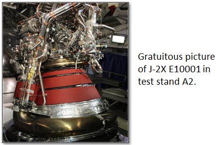
Design and Development
Specific technical requirements — There is a small handful of specific technical requirements that effectively flow down from NPR 8705.2B and impact the engine design.  One is the requirement that, where appropriate and where it can be shown to increase reliability and safety, we should use redundant systems.  On the J-2X, the clearest manifestation of this is the use of an engine controller with two channels.  Should one channel fail (as even heavy-duty computer systems sometimes can), the other channel can take over and continue safe operation.  Another specific requirement at the system level is that there exist abort systems that allow the crew to escape from a bad situation on the vehicle.  This requirement decomposes to a requirement on the J-2X for a redline health monitoring system that shuts down the engine in the event of an imminent failure and notifies the vehicle of this shutdown.  This thereby allows the crew the opportunity to perform an abort.

Design, construction, workmanship standards — Not surprisingly, we don’t start from scratch every time that we sit down to design something.  We know how to do things.  We have lessons learned.  We have rules of thumb.  And, at the top of the list, we have standards.  These are specialized requirements documents that focus on specific, narrow technical areas.  For example, NASA-STD-5012 tells you what you should do for the structural design of a rocket engine.  It lays out the essential analyses to perform, the way that the environments should be evaluated, and what factors of safety are appropriate.  For J-2X, we had over thirty different standards that were (and are) part of the requirements imposed upon the engine design details, design processes, fabrication processes, and testing scope and procedures. 

Even here, however, after you impose a standard you have to acknowledge the fact that there can exist more than one way to do things and do them safely.  For example, on J-2X we imposed a structural design standard that, at a lower level, imposed a standard for how fasteners (i.e., bolts and nuts) are properly lubed and torqued.  In order to investigate this issue, we set up a mini-test program to better understand the results from the different methods.  It kind of sounds silly, but fastener torque is extremely important in high-pressure systems and proving that the contractor process was equivalent and safe could save us money in the long run since it is a standard procedure for them.  So, we had a guy follow the procedures several times and we measured the strain induced into a series of bolts by the applied torquing method.  The measured strain was converted to applied force and this thereby validated the procedure.  Across the spectrum, we had a number of similar examples where we interpreted the technical intent and purpose of a detailed requirement and, working with our contractor, found the best way to comply.

System safety program — As an engineer, the question foremost in your mind is always, “How can I make this thing work?”  Without that mindset, we would never get anywhere.  However, when dealing with something as complex and as potentially dangerous spaceflight, you must go beyond this level of thinking and must also continuously ask yourself, “What could go wrong with this thing and how do I mitigate that potential as much as possible?”  In the most basic sense, this is the motivation for developing a system safety program.  As part of the engine design and development process, you look at this issue from two directions. 

First, you look at the piece-part level and ask, “What could break, how or why, and what would be the effects?”  That’s a reliability analysis.  You look at all of the pieces and figure out what circumstances could result in something not working as intended.  Could the design be mistaken because we didn’t understand the loads?  Could the loads go off nominal because of some unusual flight situation?  Could the manufacturing of that piece go awry so that you don’t have the intended design margins in the actual, physical part?  And, for all of these questions, you have to provide answers as to how best to ensure that the part won’t actually break during operation.

Second, you start from the other end.  You start with the grim notion that you’ve failed and that the crew didn’t make it.  From there you work backwards and figure out how and why that situation could take place.  This process grows into a tree of circumstances and possibilities and is called a hazards analysis.  Was it an explosion?  If so, where did the fuel and oxidizer and ignition source come from?  If the fuel came from tank, then how did it escape?  Was it instead something having to do with navigation?  Or maybe there was a weather-related issue, perhaps, say, lightning? 

Obviously, in many places these two assessments eventually meet in the middle.  The one starts at the bottom and works upwards.  The other starts at the top and work downwards.  When they meet, then you know where throughout your system are your critical points.  In some cases this drives design features, special inspection requirements, or, for example, in the case of lightning protection, the design and construction of a launch pad system for dealing with the hazard.  This overall effort allows you to prioritize your efforts to ensure safety and, in the operational phase, potentially apply greater attention prior to committing to launch. 
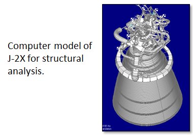
Test and Evaluation
Structured verification planning and reporting — Believe it or not, we don’t march into an engine test program all willy-nilly and make a bunch of smoke and fire just for the sake of impressing our friends.  We do it to generate and collect data.  The data that we collect largely goes towards the systems engineering endeavor known as requirements verification.  Verification is defined as the process of demonstrating that the product design — in our case an engine — is in compliance with imposed requirements.  Verification can, and does, take a number of forms.  Testing is one form.  Analysis and inspection are others. 

Note that the “structured” part of the “structured verification” title above is a key consideration.  You must lay out plans saying, “Here is my requirement and here is what I plan to do to prove that I meet it.”  Then, based upon peer review of experts, this plan can be approved or modified.  This is an essential part of the whole judgment aspect of human rating.  If I demonstrate that I meet the requirement with one engine on one test, is that good enough?  If not, how many engines or tests do I need?  Or, if it’s verification by analysis, do you agree with the analysis methodology that we propose to use?  Do you concur with the assumptions and the simplifications inherent in any analysis method?  The whole process, when properly approached, has the flavor of the classic scientific method.  The hypothesis is that the product meets the requirement and then you set out to prove that hypothesis.

Smart people with backgrounds in mathematics inevitably jump into the conversation here and declare the supremacy of statistics.  Using statistical analysis, we can determine how many samples and tests are necessary to achieve a mean and variability assessment at a given confidence level.  Unfortunately, as good as those methods might be, we can never come close to affording the kinds of programs that a purely statistically based assessment would suggest.  Maybe back in the day we could afford to build and test 100 engines before we’re ready to fly, but today our constraints are to accomplish the same level of risk mitigation with an order of magnitude fewer samples.  We have to be wiser and more efficient, and yet still have sufficient confidence to declare that the design meets its requirements.

Test, test, test, and then test some more — Now, after having discussed a fundamental motivation for testing engines, i.e., requirements verification, you have to get down to the nuts and bolts of the issue.  You must test and you must do it a lot.  Yes, “a lot” is not what you’d call a scientific term, but it can be decomposed.  “A lot” means that you cover your verification plans in terms of samples and repeat examples.  It means that you push things beyond normal operation to prove margins.  You test longer — both single run and cumulative on a given engine, both starts and seconds — than any flight engine could possibly ever see.  And throughout this process, you continuously learn things that you didn’t know that you didn’t know.  While it is theoretically possible that we could design an engine, put it into test, and find that we’d properly characterized every environment and every engine response to those environments, but I’ve never seen such a case and nobody that I know have ever heard of such a thing.  Engine testing is always an education.
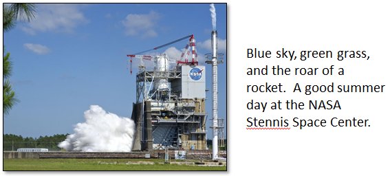
The other aspect of testing that is sometimes categorized separately is teardown and detailed inspection of the hardware afterwards.  If you predicted that something wasn’t going to crack and, upon teardown, you find a crack where it shouldn’t be, then you’re not as smart as you thought you were (a phrase I’ve used before).  If you tear down and find that something was rubbing in a valve or a turbopump, then that might be an issue.  Or, instead, it might have been planned that way.  You look for discoloration that might suggest unexpected operational conditions or potential changes in material properties.  You check dimensions of everything to make sure that you didn’t deform pieces or possibly lose material that was consumed by the engine.  Thus, while you collect lots and lots of data during the engine tests, it is also the data that you collect after the testing is complete that contributes substantially to your understanding of the design and its safe operation. 

Operations
Quality processes — Twenty-some years ago, the Ford Motor Company had a motto that they used in advertising: “Quality is Job One.”  With all due respect to that venerable motor company, those of us in the rocket world have known this for a long, long time. 

When we certify an engine design and say that it is “human-rated,” that is a contingent description.  It is contingent upon future flight engines being produced in the same manner and to the same detailed workmanship standards as the design that you certified.  That means that the fabrication and testing processes are the same, the materials are the same, the people doing the work on the pieces have had the appropriate training, and that the finished parts have been scrutinized to the same inspections and inspection standards.  And, if things can’t be exactly the same (for example, vendors can change over time), then you must have a process in place to assure equivalence between what you had before and what you’re going to use new. 

Also, should something go awry during the manufacturing or assembly of any part — and things always go awry to some degree at some point — you need to have processes in place to identify what went wrong, how to avoid that issue in the future, and what to do with any hardware that was exposed to the issue.  Can you fix it and still meet your requirements and drawing specifications?  Or, do you have to scrap the part because it can’t be saved? 

These considerations are all part of a good, solid quality system.

Configuration management — The first cousin of quality assurance is configuration management.  While it sounds like a simple premise, this discipline deals with making sure that the exact, particular pieces on the vehicle are the exact, particular pieces that you intended to put on the vehicle.  This means, for example, that every bolt on the engine is suitable for a flight engine.  No, not every bolt has a serialized part number, but they are segregated by lots.  Lots intended for flight usage are subjected to a stringent quality processes and must, therefore, be kept separate from any similar-looking bolts that might not meet the high standards for flight.  Plus, of course, we track throughout their lives the history of our serialized assemblies like turbopumps, combustion chambers, nozzles, ducts, lines, controllers, valves, etc., along with their associated documentation.  And engine is composed of thousands of parts and, one way or another, we track them all. 

The combination of a good quality assurance system and a good configuration management system guarantees that what you have delivered and put on the launch vehicle is exactly what it is advertised and intended (and needs) to be.

That’s it.  Those are, in my opinion, the key ingredients for human rating.

So, getting back to cooking.  In order to make vegetarian chili, you need tomatoes, beans, and chili powder.  That’s it.  But chili made with just these ingredients would be terrible.  I add peppers (of multiple varieties) and onions and garlic and other spices.  Corn can add a nice sweetness.  Sometimes I sauté chopped portabella mushrooms and toss them in.  Beyond that, I’ve been known to add all kinds of oddball stuff including, once, green beans.  And, in the end, it’s good.  I promise.  That’s because I’ve made it probably thirty or forty times over the years and therefore I am a subject matter expert (within my tiny culinary world).  Solid, well-defined ingredients and expert judgment inform my chili.

In order to have a “human-rated” rocket engine, all of the topics that I mention above represent the key, essential ingredients: (1) a few, specific human-rating design requirements, (2) a set of established design, construction, and workmanship standards, (3) a thorough safety program, (4) a structured verification process, (5) system testing campaign, (6) a solid quality assurance system, and (7) a reliable configuration management system.  They are all necessary.  And certain bounds, limits, or standards can be established (and are documented) for all these various disciplines and undertakings, but an exact, repeatable, or universal, step-by-step recipe is extremely difficult to conjure up.  Just like my chili, the details of how, when, and why an engine is “human rated” fall within purview having good key ingredients and then applying expert judgment.


J-2X Progress: Two Stands Occupied

It’s been awhile since I’ve had the opportunity to update what we’ve been doing for the J-2X development test campaign.  So, everyone is probably wondering where we stand.  Well, if possession is nine-tenths of the law, then J-2X IS THE LAW for the NASA Stennis Space Center A-complex!  Right now, the J-2X development effort has our PowerPack Assembly 2 in test stand A-1 and Engine 10001 has been reinstalled on test stand A-2.

Below are two pictures of the J-2X PowerPack Assembly 2 (known as PPA2) taken from different perspectives.  In the second one, you can see that several pieces are coated with ice.  That’s obviously a picture with cryogenic propellants loaded in the ducts and turbomachinery.  In other words, to use our local jargon, in the second picture PPA2 is chilled down.

Well, you saw in a previous blog article that we spun up the PPA2 and we demonstrated ignition of the gas generator.  Beyond that, however, we’ve had a few hiccups.  For the first test intended to get to mainstage operation, we didn’t get very far.  We effectively demonstrated again the spin start and ignition of the gas generator.  Immediately beyond that, just a few tenths of a second in fact, the test shut down due to an issue on the facility side.  As I’ve described before, the PPA2 is kind of an odd beast in that it’s a half-engine and half-facility test article.  In this case, a facility valve did not function the way that it was supposed to.  It was sluggish.  A subsequent investigation into the facility hydraulic system identified and fixed the issue so we were again all ready to go.

On the next test we got a little farther but just before getting to mainstage, we busted an engine-side redline limit and had to shut down early.  The reason for that early cut was actually quite analogous to the early cut we had on our first attempt at a mainstage test for Engine 10001.  We didn’t quite understand the characteristics of the engine components and so, as we powered up the system, we were headed towards an operating point different than we’d intended.  In other words, our calibration was a bit off.  The redline system identified this situation and, properly, cut off the test before anything damaging might occur.  While early cuts are sometimes a pain in the neck, we have those safety systems built in there for a reason.  There is always a substantial and meaningful difference between a nuisance and something potentially worse. 

Over the course of the next couple of PPA2 tests we once again proved that hydrogen is a pernicious rascal.  This is something that has been proven on many former occasions throughout the history of rocket engine development.  If you give hydrogen any opportunity to leak, any at all, it will.  And sometimes, it will only leak when the system is chilled down so that when you’re checking out the system before a test, when you’re searching for potential leaks, you don’t see a thing.  But then, when you are all set up and get the test going, ta-da, you suddenly have a fire.  Why a fire?  Because with a hydrogen leak around all the rest of the hot stuff going on with the test, a leak almost always becomes a fire.  And, because pooled, un-burnt hydrogen is a potential detonation hazard, we also have devices all around the vicinity of the test article designed to make sure that any leaked hydrogen gets burnt.  So, quite simply: hydrogen leak on engine test = hydrogen fire on engine test.  The fires that we saw on these two tests were not on the “engine” half of the PPA2 test article per se.  Instead, we got fires on the facility half.  The emergency systems in place for such issues include cameras and temperature probes so that there was practically no damage and our hardware is just fine.  But the fires did mean that we’ve accumulated only a limited amount of mainstage data so far.

Undaunted, we have investigated and, we believe, solved the issue and will once again be ready for testing in the near future.

On the other test stand, specifically stand A-2, the folks at the NASA Stennis Space Center have been darn busy.  If you go back a couple of months in these blog articles you’ll find a discussion about the next phase of testing for J-2X development engine 10001 (E10001 for short).  In that article, I tell you all about the test stand passive diffuser and the engine nozzle extension that we’ll be testing.  Well, the first thing that we had to do to make this next phase for E10001 possible was to modify the test stand.  In order to make the passive diffuser function properly, you have to effectively seal off the top.  

In the picture above you’ll see what’s called the clamshell.  This two-piece device rotates out of the way for access to the engine between tests but during a test wraps around the nozzle of the engine on the top side and connects to the diffuser on the bottom side.  We’ll use a rubber-ish seal in the gap between the clamshell and the nozzle to maintain the seal while accommodating movement of the nozzle during hot fire testing.  Getting this thing designed, built, and into the stand was a heck of a lot of work.  The folks who accomplished this deserve mucho kudos.

So, that’s the test stand side.  Next, there is the test article side, i.e., the engine itself.  Because the nozzle extension is not structurally beefy enough to support the rest of the engine, the installation of the test article into the stand has to be performed in two steps.  First, you install the main part of the engine and then, once that’s in place, you install the nozzle extension. 

By the way, while it sounds easy enough to simply bolt the nozzle extension into place on the end of the nozzle, it’s actually a bit more complicated.  While both pieces are designed to be exactly round, nothing is truly exactly round, especially not pieces of hardware this large.  We have to use special “rounding” tools during the mating process.  It’s sometimes amazing to think about all of the specialized tools and equipment that you need, in addition to the engine itself of course, just to make the engine work. 

So, that’s where we stand in terms of our development test campaign.  As if southern Mississippi isn’t hot enough in the summer, J-2X will soon be adding even more heat from two active test stands very, very soon and for several months to come.  Elsewhere, FYI, we’re working on various stages of fabricating and/or assembling J-2X development engines 10002 and 10003.  They will be what follows PPA2 and E10001 into the test stands.  In other words, there’s lots of excitement yet to come.

Welcome to the J-2X Doghouse: Twist and Shout…and Steering

Put a little kid into the driver’s seat of a (safely parked) car and what’s the first thing that they do?  They grab the steering wheel and twist it back and forth.  Twisting the steering wheel back and forth is just about the most intuitive, intrinsic — practically instinctive — sense of “driving” that I can imagine.  Even the handlebars of a bicycle or a motorcycle fit into the same idea.  Can you think of driving a car or a boat or, well, anything, without a steering wheel (of some sort)?  It’s tough, isn’t it?  


Okay, now think of a launch vehicle blasting off the pad and upwards heading towards the sky.  Other than for some extreme, emergency conditions, there is not anything that stands in for the steering wheel on a launch vehicle during ascent.  The process of steering the vehicle requires such precision and responsiveness that it has to be automated.  Sorry Buck Rogers, the computer is flying the vehicle.  But, even without a steering wheel, per se, how does steering happen?

With a car, you point the front wheels and, thanks to friction between the tires and the road, you get pulled (or pushed for the sports car purist and NASCAR fans) in that direction.

With a boat, you use a rudder so that the water pushing against it points the boat in the direction you want to head.

With an airplane, you have to use a combination of aerodynamic surfaces since you’re now dealing with steering in three dimensions, not just two as with an automobile or a boat.  But the idea is basically the same: the air through which you’re moving pushes against the aerodynamic surfaces and points the plane in the direction you need to go.

What do you do with a launch vehicle?  Not long after the first couple minutes of flight, you’re so high in the atmosphere that there’s not enough air to effectively use aerodynamic surfaces.  In other words, you don’t have a road and a rudder won’t work.  So what do you use when you don’t have anything against which to push?  That’s right: a rocket!

You could, if you chose to do it this way, use dedicated steering rockets.  We do use these when we’re in space and we typically call them “retrorockets” or “reaction and control” rockets.  But during the ascent, you already have a big rocket engine pushing you along so you might as well use that if you can, but to do so, you need to twist it around…


[Yes, I can’t help myself.  I had to make a musical reference.  “Twist and Shout” (written by Phil Medley and Bert Russell) was originally recorded by the Top Notes, then the Isley Brothers, and, eventually by the Beatles (as so memorably replayed many years later in “Ferris Bueller’s Day Off”).  Lots and lots of people have done versions of this song, but probably the most bizarre was Mae West — yes, THAT Mae West — when she was 72 years old.  Who knew?]

What do I mean with regards to twisting a rocket engine?  Here’s a video of what we call “gimballing” an engine on the test stand, in this case a Space Shuttle Main Engine (video provided by my friend and coworker Rick Ballard from his Liquid Rocket Engine class materials):


So, for a launch vehicle during ascent, you accomplish steering by pointing the thing pushing you, i.e., your main propulsion rocket engine.  That’s a cool video, huh?  But how do we accomplish that?  The movement itself is provided by hydraulic actuators.  These are push/pull devices driven by fluid pressure.  The brakes on your car are hydraulically actuated, for example.  Another example of hydraulic actuators are those lifts at the garage they use to pick your car up off the ground.  In other words, they can be very powerful devices.  You can do a quick web search on “hydraulic actuators” and find all kinds of pictures and articles and even sales pitches from manufacturers.  


On the rocket engine we put just two connection points for the actuators at ninety degrees apart from each other.  This gives us what you can think of as full, two-dimensional coverage.  If you remember back to math class, everything on a flat page can be located via X-Y coordinates.  Thus, one actuator provides the X-direction and the other provides the Y-direction.  And, with that, we can point the engine to any location within a given, limited range of movement.
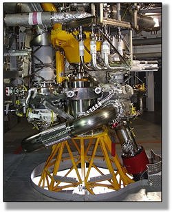
At the top of the engine, in order to allow the movement, we put in what amounts to a universal joint.  It’s called the “gimbal bearing” and it’s like the ball-and-socket joint in your shoulder except that this joint has to carry the full thrust load of the engine while maintaining its flexibility.  Because of the conditions seen by the engine, you can’t use any typical lubrication like grease or anything like that.  Instead, we use a Teflon-impregnated fabric layer.
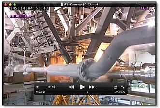

I like the picture above showing several guys working with typical engine gimbal bearings.  In the picture you can get a sense of how beefy these things are when assembled and you can clearly see the “ball” part of the ball-and-socket joint. 

Have we gotten to the really, really neato part yet?  Yes, we have (in my humble opinion).  Here it comes.  How is it that we can move around the engine?  I mean, besides the big ball-and-socket joint at the top that is meant to move around, all the rest of it is assembled out of all kinds of stiff metal pieces, right?  It’s not like you can stick cryogenic propellants through a flexible rubber garden hose.  So how do we get the compliance in the rest of the engine components that allow for the movement the actuators and gimbal bearing are providing?  With no compliance, the actuators would push and pull, and, assuming that they were powerful enough to do damage (and they usually are), the engine ducts would buckle and crush and, frankly, you’d have a crumpled mess.  What we do then is build the compliance into the engine with specific parts to provide this functionality.  This is accomplished in different ways on different engines.  Below is how this compliance is accomplished for J-2X for the main propellant lines:


That pretty piece of hardware is a propellant inlet duct.  In fact, that picture is of the first new propellant inlet duct fabricated for a J-2, J-2S, or J-2X engine in forty years.  This new duct is like the heritage design but better, safer, more robust.  It is an extremely difficult piece of hardware to make in that it involves some very highly specialized welding techniques.  So a big shout-out goes to Pratt & Whitney Rocketdyne and the guys on the shop floor.  Way to go guys!


How does it work?  The sections with the convolutions are called bellows.  Above is a cut-away of a metal bellows made by the same company as our propellant inlet duct, Gardner Bellows Corporation, but not our same design.  The bellows take advantage of the way that metal can act like a spring.  If it doesn’t get bent too far, the metal will bounce back undamaged.  These dozens of convolutions in the bellows allow for enough movement that the whole thing acts like a stiff spring.  The hinged structures on the sides hold the bellows together and constrain the springy parts and make sure that they stay in their groove (so to speak). 

The next natural question about this duct is this:  Why does it appear to be in two pieces, an upper bellows and a lower bellows?  The answer is that it isn’t in two pieces; it’s in three pieces.  In between the upper bellows and the lower bellows is a third set of bellows that you can’t see very well and that’s because they’re really flat.  This is the torsional bellows and it provides for a slight twist between the upper and lower sections.  When you’re gimballing the engine, not only do you need these ducts to bend, you also need a bit of twist…


I think that the torsional bellows is even cooler than the bending bellows.  Have you ever tried to twist a long piece of wood, like maybe an eight-foot-long, one-by-two strip?  The longer the piece, the easier it is to get a few degrees of twist.  A short piece of wood, even with the same cross-sectional dimensions, won’t allow for as much twist.  There is an “allowable twist per unit length” thing going on: longer = more twist, shorter=less twist.  Okay, now assume that the same is true for a metal pipe.  If you have a very long metal pipe and you apply a twisting force to it (torsion), you can get some movement, more movement than you’d get with a short pipe.  But there’s no space on a rocket engine for a very long pipe, so how do you allow for some twist?  What we do is collapse the long pipe into shortness by making it into a very tight accordion-like package.  In other words, we add convolutions kind of like the bending bellows, but make them very tight, very flat.  So, all of the metal “length” is still there, just in a really compact, squashed package.  It kind of feels like cheating, somehow, but it works.  See?!  That’s just neato!

In addition to the big ducts, the propellant ducts, you also have to take into account any other connections between the engine and the vehicle stage.  If you think back to the article about vehicle integration, you’ll remember that we’ve got pneumatic lines and propellant pressurization lines and helium spin start lines connecting the engine to the stage.  In all of these lines we have to make provisions for compliance to engine gimballing motion.  As you can imagine, this makes the design for these pieces not simple.  But nobody ever said that rocket engines were supposed to be simple.  Also note that different rocket engines use different approaches for achieving the compliance necessary to accommodate gimballing, but they almost always use “springy” metal bellows in some sort of configuration.

The first J-2X engine that will see gimballing in the test stand will be development engine E10002.  That should be happening later this year.  Stay tuned.  I’ll certainly be posting some gee-whiz video after that happens.  Go J-2X!