Orion Spacecraft Recovery Rehearsal Underway

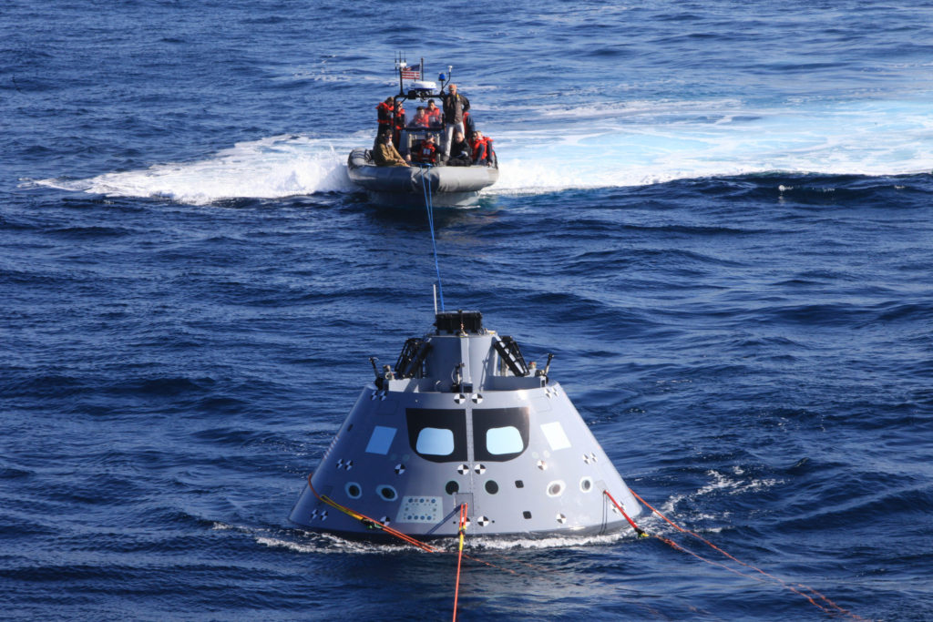
As part of Underway Recovery Test 6, the Orion test article is pulled in by a winch line at the rear of the USS Anchorage’s well deck that brings the capsule into the ship, along with four manned LLAMAs (Line Load Attenuation Mechanism Assembly) that control the capsule’s side-to-side movement and a tending line attached to a rigid hull inflatable boat for controlling Orion’s movement behind the ship. Photo credit: NASA/Bill White

NASA’s new deep space exploration systems will send crew 40,000 miles beyond the Moon, and return them safely home. After traveling through space at 25,000 miles per hour, the Orion spacecraft will slow to 300 mph after it passes through the Earth’s atmosphere. The spacecraft then slows down to 20 mph before it safely splashes down in the Pacific Ocean.

When astronauts come back from deep space, they will need to be picked up as quickly as possible. That’s where Kennedy Space Center’s NASA Recovery Team comes in.

Under the auspices of Exploration Ground Systems, Melissa Jones, NASA’s recovery director, and her team will recover the Orion capsule and crew. NASA and the U.S. Navy are working together to ensure they are ready before the first uncrewed Orion mission aboard the agency’s new Space Launch System rocket, known as Exploration Mission-1.

This week, the integrated NASA and U.S. Navy team are aboard the USS Anchorage, testing out new ground support equipment and practicing their procedures.

After Orion completes its mission out past the Moon and heads to Earth, Jones will get the call Orion is coming home. Then, it is her job to get the joint NASA and U.S. Navy team to the capsule’s location quickly and bring it and the astronauts safely aboard the U.S. Navy recovery ship.

“We are testing all of our equipment in the actual environment we will be in when recovering Orion after Exploration Mission-1,” Jones said. “Everything we are doing today is ensuring a safe and swift recovery when the time comes for missions with crew.”

Crew Access Arm for Space Launch System Arrives at Kennedy

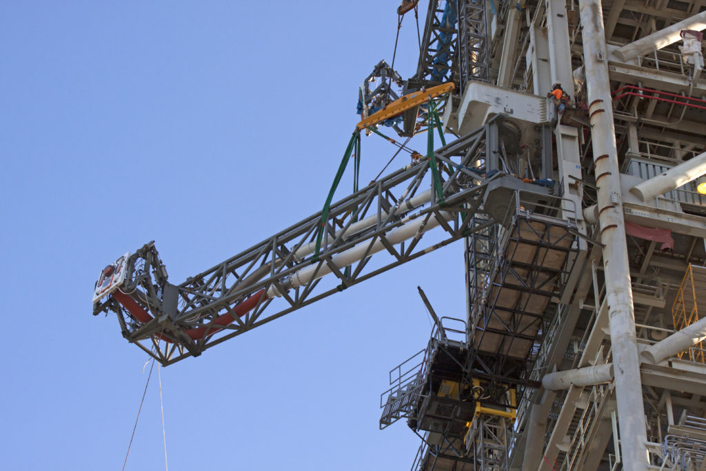
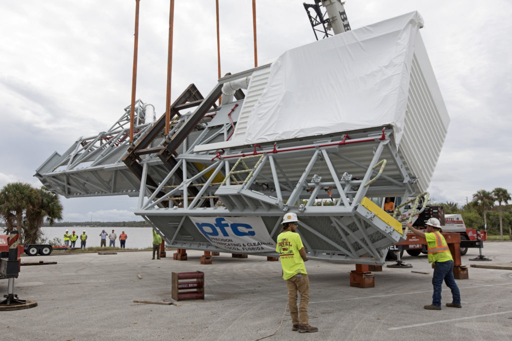
Two heavy-lift cranes are used to tilt and lower the Orion crew access arm onto a work stand in a storage location Oct. 17, 2017, at NASA's Kennedy Space Center in Florida.
Two heavy-lift cranes are used to tilt and lower the Orion crew access arm onto a work stand in a storage location Oct. 17, 2017, at NASA’s Kennedy Space Center in Florida. The access arm was transported from Precision Fabricating and Cleaning in Cocoa, Florida. Photo credit: NASA/Kim Shiflett

When astronauts depart for missions to deep space, they will cross the Crew Access Arm about 300 feet above the ground to board their spacecraft. The access arm was delivered to NASA’s Kennedy Space Center in Florida on Oct. 17, 2017, to install on the mobile launcher in preparation for the first flight of the Space Launch System rocket, or SLS, and the Orion spacecraft.

The SLS will be the largest rocket in the world and will be stacked with Orion inside the historic Vehicle Assembly Building, or VAB, on the mobile launcher and rolled out to the pad prior to launch. The access arm will be one of 11 connection points to the rocket and spacecraft from the tower on the mobile launcher. After technicians install the arm, the mobile launcher will be rolled into the VAB for validation and verification tests.

For the first launch without crew, the access arm will provide a bridge to Orion for personnel and equipment entering the spacecraft during processing and prelaunch integrated testing while in the VAB and at the launch site. The arm is made up of two major components: the truss assembly and the environmental enclosure, or the white room. The arm will provide entry and emergency egress for astronauts and technicians into the Orion spacecraft. On future human missions, astronauts outfitted with newly designed space suits will enter the white room, where they will be assisted by technicians into the spacecraft for launch. The arm will retract before launch, and the other connections will release at liftoff, allowing the rocket and spacecraft to safely clear the launch pad.

New Umbilical Fitted for Mobile Launcher to Support NASA’s Deep Space Exploration Missions

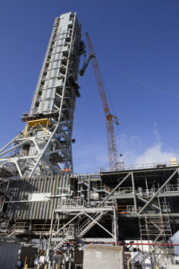
A fit check of the core stage inter-tank umbilical is in progress on the mobile launcher tower at Kennedy Space Center in Florida
High up on the mobile launcher tower at NASA’s Kennedy Space Center in Florida, construction workers assist as a crane moves the Core Stage Inter-tank Umbilical into place for a fit check of the attachment hardware. Photo credit: NASA/Glenn Benson

Engineers lifted and installed a third umbilical on the mobile launcher at NASA’s Kennedy Space Center in Florida for a fit check. The tower on the mobile launcher will be equipped with several connections or launch umbilicals like this one. After the fit check was completed, the umbilical was lowered down and will be installed permanently at a later date.

The umbilicals will provide power, communications, coolant and fuel. They will be used to connect the mobile launcher to the agency’s Space Launch System (made up of the core stage, twin solid rocket boosters, and the interim cryogenic propulsion stage) and the Orion spacecraft mounted on top of SLS.

An area on the SLS between the liquid hydrogen and liquid oxygen tanks is known as the core stage inter-tank. The core-stage inter-tank umbilical is the third in a series of five new umbilicals for the mobile launcher. Its main function is to vent excess gaseous hydrogen from the rocket’s core stage. This umbilical also will provide conditioned air, pressurized gases, and power and data connection to the core stage.

The Orion service module umbilical and the core stage forward skirt umbilical were previously installed on the tower. The service module umbilical will connect from the mobile launch tower to the Orion service module. Prior to launch, the umbilical will transfer liquid coolant for the electronics and purge air/gaseous nitrogen for environmental control. The SLS core stage forward skirt is near the top of the core stage, and the forward skirt umbilical provides connections and conditioned air/gaseous nitrogen to the core stage of the rocket. All these umbilicals will swing away from the rocket and spacecraft just before launch.

Several other umbilicals were previously installed on the mobile launcher. These include two aft skirt purge umbilicals, which will connect to the SLS rocket at the bottom outer edge of each booster and provide electrical power and data connections, remove hazardous gases, and maintain the right temperature range with a nitrogen purge in the boosters until SLS lifts off from the launch pad.

The Ground Systems Development and Operations Program at Kennedy is preparing ground support equipment, including the launch umbilicals, for NASA’s deep space exploration missions.

Liquid Oxygen Tanking Operations Begin at Launch Pad 39B

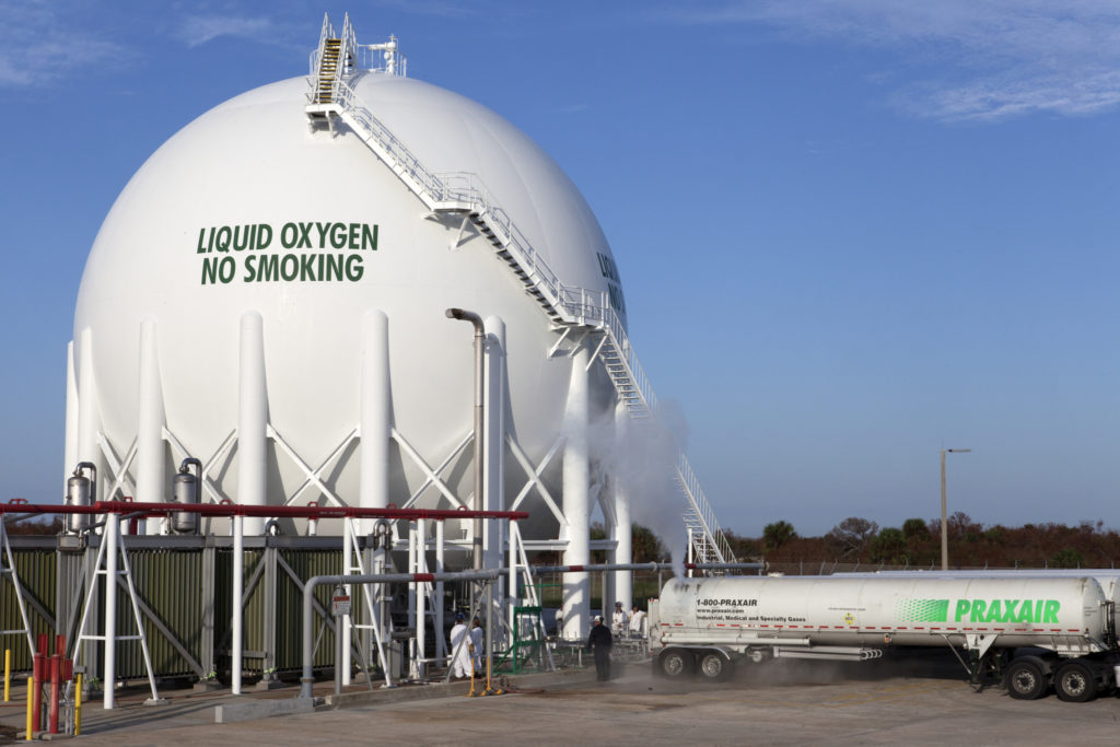
Praxair trucks offload liquid oxygen into a giant storage tank at Launch Pad 39B at Kennedy Space Center in Florida.
Several Praxair trucks carrying their loads of liquid oxygen, or LO2, arrived at Launch Pad 39B at NASA’s Kennedy Space Center in Florida. A mist is visible as LO2 is offloaded from one of the trucks into the giant storage sphere located at the northwest corner of the pad. Photo credit: NASA/Kim Shiflett

The first major integrated operation at Launch Pad 39B at NASA’s Kennedy Space Center in Florida began with the initial tanking of a cryogenic fuel into a giant sphere at the northwest corner of the pad. The tanking operation is one of the steps needed to bring the center closer to supporting the launch of the agency’s Orion spacecraft atop the Space Launch System rocket on its first uncrewed test flight.

“When I think of launch operations, there are distinct pictures that come to mind,” said NASA Launch Director Charlie Blackwell-Thompson. “One of them is during the tanking operations as the cryogenic propellants are loaded into the Space Launch System rocket.”

Several Praxair trucks arrived at the center and offloaded their liquid oxygen, or LO2, slowly, one at a time, into the cryogenic sphere to gradually chill it down from normal temperature to about negative 298 degrees Fahrenheit. Praxair, of Danbury, Connecticut, is the company that provides the agency with liquid oxygen and liquid hydrogen.

Another wave of trucks arrived and offloaded their LO2 all at the same time. During the next several months, trucks will continue to arrive from Praxair and offload about 40,000 gallons of fuel two days per week into the sphere that can hold about 900,000 gallons of liquid oxygen.

The procedure to fill the liquid hydrogen storage sphere will begin in November and will be completed in the same way. When both tanks are filled to about halfway, engineers in a firing room in the Launch Control Center will perform pressurization tests. Additional tests will be performed with the mobile launcher around mid-2018. The cryogenic fuels will remain in the tanks.

Blackwell-Thompson said it is not uncommon during tanking to see vapors and mist in the cryo storage area and near the vehicle. This week, she got a preview, when the trucks offloaded the first round of LO2 and once again, cryo vapors were visible. Because some of the liquid oxygen boils off during tanking, additional LO2 is required.

“This is a very important step in our path to launch, and we are thrilled to have cryo propellant return to the pad,” Blackwell-Thompson said.

The Ground Systems Development and Operations Program is preparing the pad for the launch of Exploration Mission-1, deep space missions and the Journey to Mars. Significant upgrades to the pad include a new flame trench beneath the pad and a new flame deflector.

Service Platforms Arrive for Space Launch System Booster Engines

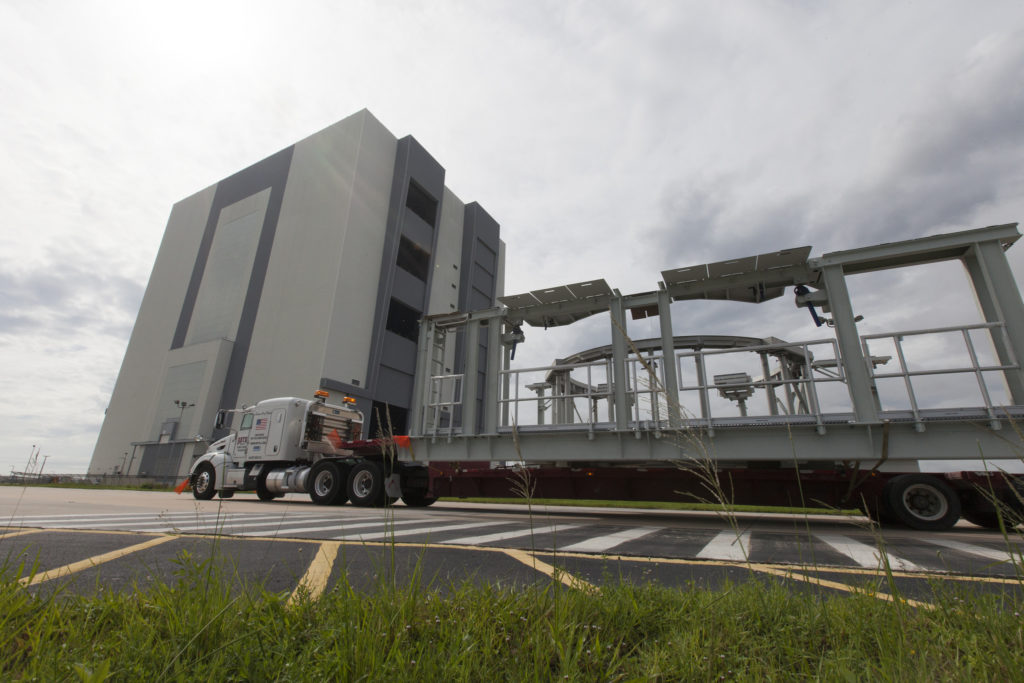
SLS booster service platforms arrive at Kennedy Space Center in Florida.
A flatbed truck carrying one of two new service platforms for NASA’s Space Launch System booster engines arrives at the Vehicle Assembly Building at the agency’s Kennedy Space Center in Florida on July 31, 2017. Photo credit: NASA/Bill White

New service platforms for NASA’s Space Launch System (SLS) booster engines arrived at the agency’s Kennedy Space Center in Florida. The platforms were transported on two flatbed trucks from fabricator Met-Con Inc. in Cocoa, Florida. They were offloaded and stored inside the Vehicle Assembly Building (VAB).

The platforms will be used for processing and checkout of the engines for the SLS’ twin five-segment solid rocket boosters for Exploration Mission-1 (EM-1). The boosters, in combination with the rocket’s four RS-25 engines, will produce more than 8 million pounds of thrust at liftoff.

The first SLS mission, EM-1, will launch an uncrewed Orion spacecraft to a stable orbit beyond the Moon and bring it back to Earth for a splashdown in the Pacific Ocean. The mission will demonstrate the integrated system performance of the rocket, Orion spacecraft and ground support teams prior to a crewed flight.

Core Stage Forward Skirt Umbilical Installed on Mobile Launcher

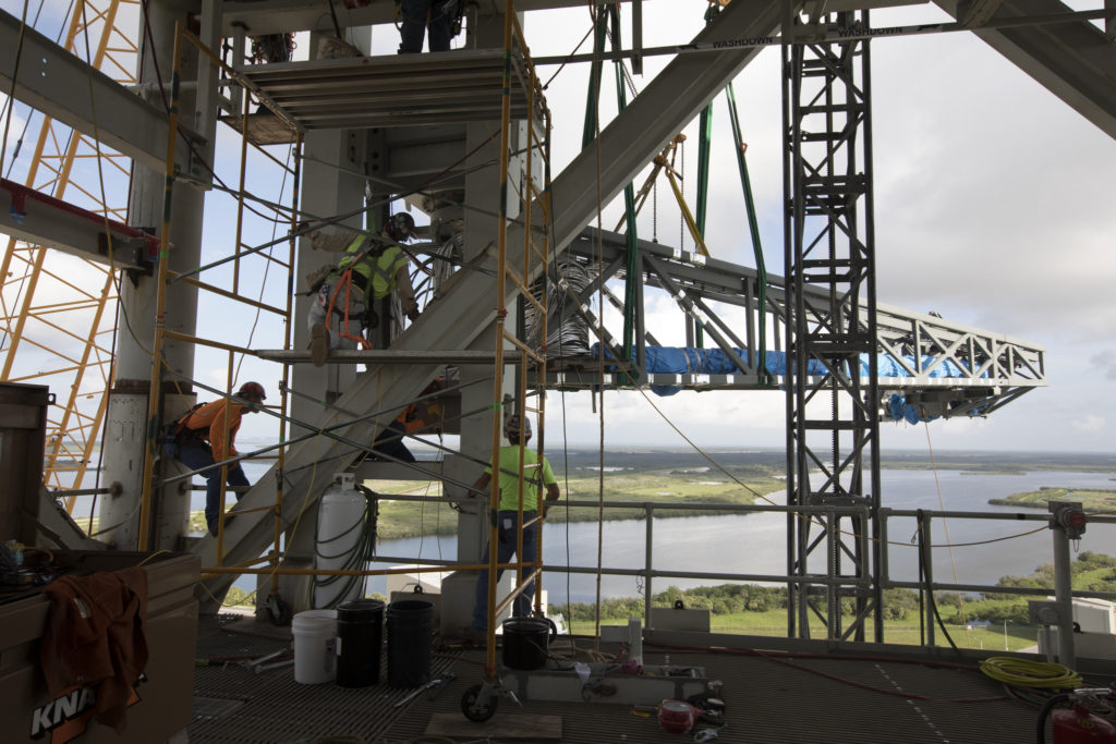
Just north of the Vehicle Assembly Building at NASA's Kennedy Space Center in Florida, technicians install the core stage forward skirt umbilical on the mobile launcher.
Just north of the Vehicle Assembly Building at NASA’s Kennedy Space Center in Florida, technicians install the core stage forward skirt umbilical on the mobile launcher.

Just north of the Vehicle Assembly Building at NASA's Kennedy Space Center in Florida, a crane lifts the core stage forward skirt umbilical for installation onto the mobile launcher.The Core Stage Forward Skirt Umbilical (CSFSU) recently was installed on the tower of the mobile launcher at NASA’s Kennedy Space Center in Florida, to prepare for the first launch of the agency’s Space Launch System (SLS) rocket with the Orion spacecraft atop.

The mobile launcher tower will be equipped with a number of lines, called umbilicals, which will connect to the SLS and Orion spacecraft and provide commodities during processing and preparation for launch of Exploration Mission-1.

Cranes and rigging were used to lift the CSFSU and install it at about the 220-foot-level on the tower. The CSFSU will swing into position to provide connections to the core stage forward skirt of the SLS rocket, and then swing away before launch. Its main purpose is to provide conditioned air and gaseous nitrogen to the SLS core stage forward skirt cavity.

The Ground Systems Development and Operations Program is overseeing installation of the umbilicals on the tower.

Photo credit: NASA/Kim Shiflett

Engineer’s LLAMA Design Aids Orion Recovery, Earns Innovation Award

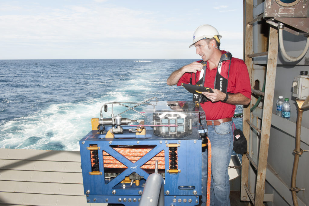
Jeremy Parr monitors the LLAMA during Underway Recovery Test 5 ion a ship n the Pacific Ocean
Jeremy Parr, a mechanical design engineer in Kennedy Space Center’s Engineering Directorate, monitors the Line Load Attenuation Mechanism Assembly, or LLAMA, on the U.S. Navy ship during Orion Underway Recovery Test 5 in the Pacific Ocean off the coast of California. Photo credit: NASA

What is a LLAMA? It’s a Line Load Attenuation Mechanism Assembly, designed by Jeremy Parr, a mechanical design engineer in the Engineering Directorate at NASA’s Kennedy Space Center in Florida. He designed the LLAMA to help U.S. Navy line handlers retrieve the Orion crew module after it splashes down in the Pacific Ocean.

Parr is the lead design engineer for Orion Landing and Recovery, which is coordinated and led by the Ground Systems Development and Operations Program. Parr’s design recently earned him second place in the agency’s third Innovation Awards competition.

“The LLAMA concept came to me after watching the sailors fighting to control the Orion test capsule during Underway Recovery Test 1 in open water in February 2014,” Parr said.

The standard Navy line tending practice is to wrap their lines around the ship’s T-bits, or large solid columns with a crossbar that resemble the letter “t,” located near the stern, so that the sailors can control big loads with only a few people. This works for most operations they do since the hardware they handle is usually big and slower moving in the seas. But the crew module is a different beast when floating in the water than anyone on the recovery team expected, Parr said. Orion is easily pushed around by wind and waves.

“I came up with a design that helps the Navy line handlers to safely maintain high tension in the tending lines during recovery of Orion into the well deck of a ship. It also regulates the amount of tension in the lines to ensure equal loading on the vehicle.”

The LLAMAs are mounted on the ship’s T-bits, and the mechanisms provide all tending line control of the crew module once it enters the well deck and until it is secured on the recovery cradle pads.

“I am both excited and honored to be recognized for the LLAMA design,” Parr said. “This has been a team effort for a few years now to get where we are today. We worked through development and testing until we completed our successful test during Underway Recovery Test 5 off the coast of San Diego in the fall of 2016.”

The LLAMA-controlled tending lines are the baseline method for recovery of Orion after Exploration Mission-1 and all future missions.

Parr began working at Kennedy in 2007. Prior to that, he worked for SAIC at Johnson Space Center in Houston for four years.

Final Brick Installed in Launch Complex 39B Flame Trench for NASA’s Space Launch System

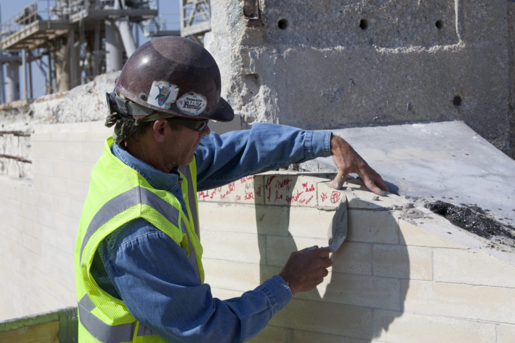
The final brick was installed on the north side of the flame trench at Launch Complex 39B.
A construction worker installs the final brick on the north side of the flame trench May 9, 2017 at Launch Complex 39B. Photo credit: NASA/Leif Heimbold

Intense heat and fire will fill the north side of the flame trench beneath the pad when NASA’s Space Launch System (SLS) rocket and Orion spacecraft lift off from Launch Complex 39B at NASA’s Kennedy Space Center in Florida. A project to upgrade the walls of the flame trench to withstand these conditions recently was completed.

All of the new heat-resistant bricks now are in place in the flame trench below the surface of the pad. Construction workers installed the final brick May 9, completing about a year’s worth of work on the walls on the north side of the flame trench to support the launch of the (SLS) rocket and Orion spacecraft on deep-space missions, including the Journey to Mars.

About 96,000 heat-resistant bricks, in three different sizes, now are secured to the walls using bonding mortar in combination with adhesive anchors. The flame trench will be able to withstand temperatures of up to 2,000 degrees Fahrenheit at launch of the rocket’s engines and solid rocket boosters.

“The flame trench has withstood so many historical launches, and we are giving it new life to withstand many more,” said Regina Spellman, the launch pad senior project manager with the Ground Systems Development and Operations Program.

The north side of the flame trench is about 571 feet long, 58 feet wide and 42 feet high.

A new flame deflector soon will be installed that will safely contain and deflect the plume exhaust from the massive rocket to the north during launch. Two side flame deflectors, repurposed from space shuttle launches, will be refurbished and reinstalled at pad level on either side of the flame trench to help reduce damage to the pad and SLS rocket.

New Ground Launch Sequencer Software Demonstrated in Launch Control Center

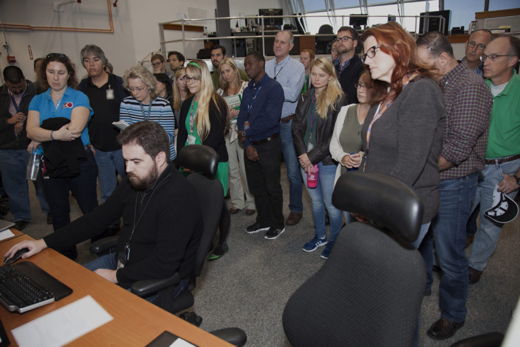
NASA engineers and test directors gather in Firing Room 3 in the Launch Control Center at NASA's Kennedy Space Center in Florida, to watch a demonstration of the automated command and control software for the agency's Space Launch System and Orion spacecraft. In front, far right, is Charlie Blackwell-Thompson, launch director for Exploration Mission 1. Photo credit: NASA/Bill White
NASA engineers and test directors gather in Firing Room 3 in the Launch Control Center at NASA’s Kennedy Space Center in Florida, to watch a demonstration of the automated command and control software for the agency’s Space Launch System and Orion spacecraft. In front, far right, is Charlie Blackwell-Thompson, launch director for Exploration Mission 1. Photo credit: NASA/Bill White

A demonstration of the automated command and control software for NASA’s Space Launch System (SLS) rocket and Orion spacecraft, recently took place in Firing Room 3 in the Launch Control Center at the agency’s Kennedy Space Center in Florida. The software, called the ground launch sequencer, will be responsible for nearly all of the launch commit criteria during the final phases of launch countdowns.

The Ground and Flight Application Software Team, or GFAST, demonstrated the software for Charlie Blackwell-Thompson, launch director for the first integrated flight of the SLS and Orion spacecraft. Also attending were representatives from the NASA Test Director’s Office.

The software is in the advanced stages of development. It includes nearly all of the core capabilities required to support the initial use during Ignition Over-Pressure / Sound Suppression and follow-on tests through launch of the agency’s SLS rocket and Orion spacecraft. The suppression stage ensures the water dampening system initiates in the final second of launch countdown. It also produces the pattern and volume needed to dampen the pressure waves and acoustic environment caused by the firing of the SLS core stage RS-25 engines and solid rocket motors.

“We were pleased to be able to demonstrate the continued evolution of the ground launch sequencer for members of the launch team, and look forward to its first use in operations support,” said Alex Pandelos, operations project engineer for Launch Integration in the Ground Systems development and Operations Program (GSDO).

The software was developed by GSDO’s Command, Control and Communications teams at the center. Development of the software will continue, with a goal of beginning verification and validation of the software in summer 2017.

Crawler-Transporter 2 Takes Test Drive Along Crawlerway

Crawler-transporter 2 with MLP-1 on top moves slowly along the crawlerway at Kennedy Space Center.NASA’s crawler-transporter 2 (CT-2) took a test drive along the crawlerway at Kennedy Space Center to determine the structural dynamics and loading environments of the crawler’s recent upgrades. The test was performed to ensure that the crawler is ready to support the first integrated flight of the agency’s Orion spacecraft atop the Space Launch System.

The unloaded CT-2 rolled from the crawler yard along the crawlerway to the Pad A/B split for the first leg of the trip and traveled back to the mobile launcher platform park site near the Vehicle Assembly Building. For the loaded test, the crawler picked up Mobile Launch Platform 1 at the park site and returned to the Pad A/B split. Engineers took measurements during the entire trek using accelerometers, strain gauges and pressure transducers. The data collected will be used to validate the dynamic model of the integrated SLS.

CT-2 is the vehicle that will carry the SLS rocket and Orion spacecraft on the mobile launcher to Pad B for launch. The behemoth vehicle recently was upgraded to support the heavier load of the SLS atop the mobile launcher.

Upgrades to the crawler included installation of new generators, gear assemblies, jacking, equalizing and leveling (JEL) hydraulic cylinders, roller bearings and brakes. Other systems also were upgraded.

The Ground Systems Development and Operations Program is overseeing upgrades to facilities and ground support equipment necessary to support the launch and deep space missions, including the Journey to Mars.

Photo credit: NASA/Leif Heimbold