Engineer’s LLAMA Design Aids Orion Recovery, Earns Innovation Award

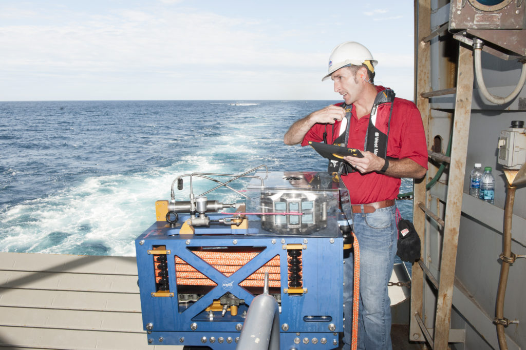
Jeremy Parr monitors the LLAMA during Underway Recovery Test 5 ion a ship n the Pacific Ocean
Jeremy Parr, a mechanical design engineer in Kennedy Space Center’s Engineering Directorate, monitors the Line Load Attenuation Mechanism Assembly, or LLAMA, on the U.S. Navy ship during Orion Underway Recovery Test 5 in the Pacific Ocean off the coast of California. Photo credit: NASA

What is a LLAMA? It’s a Line Load Attenuation Mechanism Assembly, designed by Jeremy Parr, a mechanical design engineer in the Engineering Directorate at NASA’s Kennedy Space Center in Florida. He designed the LLAMA to help U.S. Navy line handlers retrieve the Orion crew module after it splashes down in the Pacific Ocean.

Parr is the lead design engineer for Orion Landing and Recovery, which is coordinated and led by the Ground Systems Development and Operations Program. Parr’s design recently earned him second place in the agency’s third Innovation Awards competition.

“The LLAMA concept came to me after watching the sailors fighting to control the Orion test capsule during Underway Recovery Test 1 in open water in February 2014,” Parr said.

The standard Navy line tending practice is to wrap their lines around the ship’s T-bits, or large solid columns with a crossbar that resemble the letter “t,” located near the stern, so that the sailors can control big loads with only a few people. This works for most operations they do since the hardware they handle is usually big and slower moving in the seas. But the crew module is a different beast when floating in the water than anyone on the recovery team expected, Parr said. Orion is easily pushed around by wind and waves.

“I came up with a design that helps the Navy line handlers to safely maintain high tension in the tending lines during recovery of Orion into the well deck of a ship. It also regulates the amount of tension in the lines to ensure equal loading on the vehicle.”

The LLAMAs are mounted on the ship’s T-bits, and the mechanisms provide all tending line control of the crew module once it enters the well deck and until it is secured on the recovery cradle pads.

“I am both excited and honored to be recognized for the LLAMA design,” Parr said. “This has been a team effort for a few years now to get where we are today. We worked through development and testing until we completed our successful test during Underway Recovery Test 5 off the coast of San Diego in the fall of 2016.”

The LLAMA-controlled tending lines are the baseline method for recovery of Orion after Exploration Mission-1 and all future missions.

Parr began working at Kennedy in 2007. Prior to that, he worked for SAIC at Johnson Space Center in Houston for four years.

Final Brick Installed in Launch Complex 39B Flame Trench for NASA’s Space Launch System

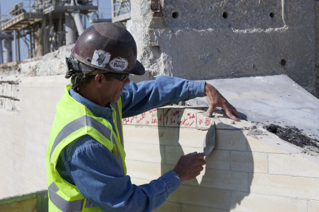
The final brick was installed on the north side of the flame trench at Launch Complex 39B.
A construction worker installs the final brick on the north side of the flame trench May 9, 2017 at Launch Complex 39B. Photo credit: NASA/Leif Heimbold

Intense heat and fire will fill the north side of the flame trench beneath the pad when NASA’s Space Launch System (SLS) rocket and Orion spacecraft lift off from Launch Complex 39B at NASA’s Kennedy Space Center in Florida. A project to upgrade the walls of the flame trench to withstand these conditions recently was completed.

All of the new heat-resistant bricks now are in place in the flame trench below the surface of the pad. Construction workers installed the final brick May 9, completing about a year’s worth of work on the walls on the north side of the flame trench to support the launch of the (SLS) rocket and Orion spacecraft on deep-space missions, including the Journey to Mars.

About 96,000 heat-resistant bricks, in three different sizes, now are secured to the walls using bonding mortar in combination with adhesive anchors. The flame trench will be able to withstand temperatures of up to 2,000 degrees Fahrenheit at launch of the rocket’s engines and solid rocket boosters.

“The flame trench has withstood so many historical launches, and we are giving it new life to withstand many more,” said Regina Spellman, the launch pad senior project manager with the Ground Systems Development and Operations Program.

The north side of the flame trench is about 571 feet long, 58 feet wide and 42 feet high.

A new flame deflector soon will be installed that will safely contain and deflect the plume exhaust from the massive rocket to the north during launch. Two side flame deflectors, repurposed from space shuttle launches, will be refurbished and reinstalled at pad level on either side of the flame trench to help reduce damage to the pad and SLS rocket.

New Ground Launch Sequencer Software Demonstrated in Launch Control Center

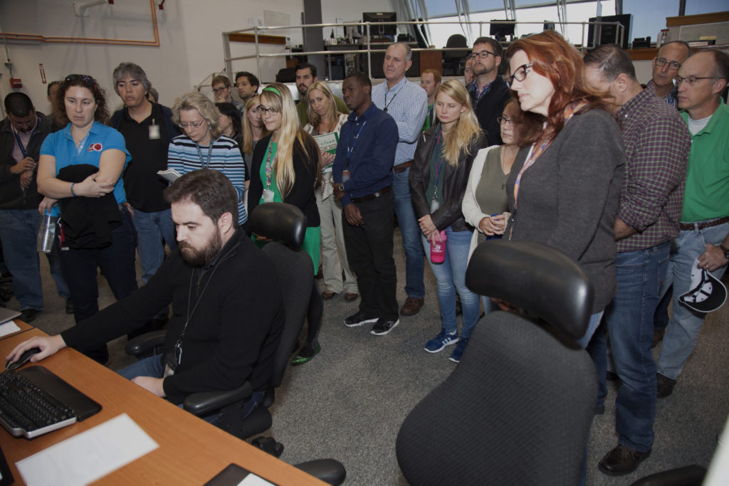
NASA engineers and test directors gather in Firing Room 3 in the Launch Control Center at NASA's Kennedy Space Center in Florida, to watch a demonstration of the automated command and control software for the agency's Space Launch System and Orion spacecraft. In front, far right, is Charlie Blackwell-Thompson, launch director for Exploration Mission 1. Photo credit: NASA/Bill White
NASA engineers and test directors gather in Firing Room 3 in the Launch Control Center at NASA’s Kennedy Space Center in Florida, to watch a demonstration of the automated command and control software for the agency’s Space Launch System and Orion spacecraft. In front, far right, is Charlie Blackwell-Thompson, launch director for Exploration Mission 1. Photo credit: NASA/Bill White

A demonstration of the automated command and control software for NASA’s Space Launch System (SLS) rocket and Orion spacecraft, recently took place in Firing Room 3 in the Launch Control Center at the agency’s Kennedy Space Center in Florida. The software, called the ground launch sequencer, will be responsible for nearly all of the launch commit criteria during the final phases of launch countdowns.

The Ground and Flight Application Software Team, or GFAST, demonstrated the software for Charlie Blackwell-Thompson, launch director for the first integrated flight of the SLS and Orion spacecraft. Also attending were representatives from the NASA Test Director’s Office.

The software is in the advanced stages of development. It includes nearly all of the core capabilities required to support the initial use during Ignition Over-Pressure / Sound Suppression and follow-on tests through launch of the agency’s SLS rocket and Orion spacecraft. The suppression stage ensures the water dampening system initiates in the final second of launch countdown. It also produces the pattern and volume needed to dampen the pressure waves and acoustic environment caused by the firing of the SLS core stage RS-25 engines and solid rocket motors.

“We were pleased to be able to demonstrate the continued evolution of the ground launch sequencer for members of the launch team, and look forward to its first use in operations support,” said Alex Pandelos, operations project engineer for Launch Integration in the Ground Systems development and Operations Program (GSDO).

The software was developed by GSDO’s Command, Control and Communications teams at the center. Development of the software will continue, with a goal of beginning verification and validation of the software in summer 2017.

Crawler-Transporter 2 Takes Test Drive Along Crawlerway

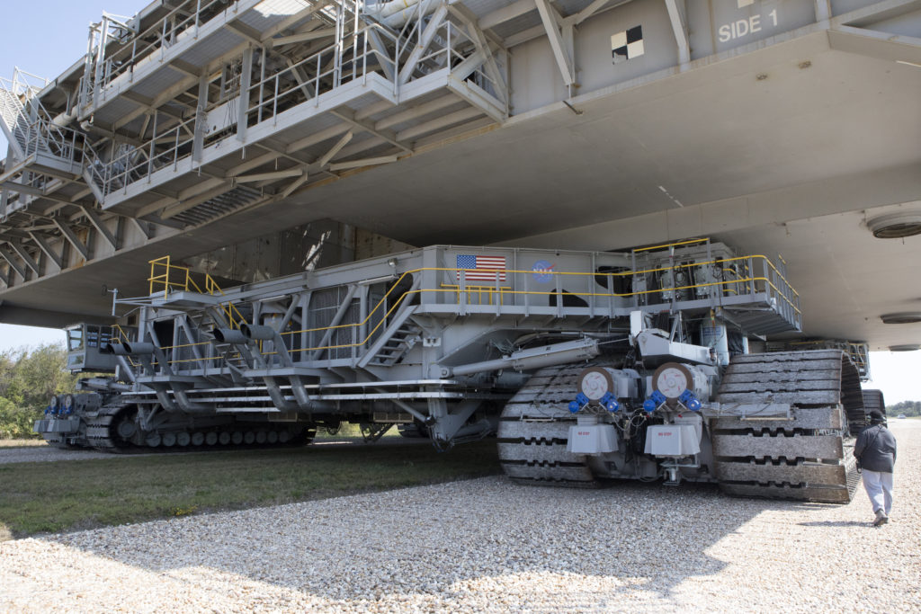
Crawler-transporter 2 with MLP-1 on top moves slowly along the crawlerway at Kennedy Space Center.NASA’s crawler-transporter 2 (CT-2) took a test drive along the crawlerway at Kennedy Space Center to determine the structural dynamics and loading environments of the crawler’s recent upgrades. The test was performed to ensure that the crawler is ready to support the first integrated flight of the agency’s Orion spacecraft atop the Space Launch System.

The unloaded CT-2 rolled from the crawler yard along the crawlerway to the Pad A/B split for the first leg of the trip and traveled back to the mobile launcher platform park site near the Vehicle Assembly Building. For the loaded test, the crawler picked up Mobile Launch Platform 1 at the park site and returned to the Pad A/B split. Engineers took measurements during the entire trek using accelerometers, strain gauges and pressure transducers. The data collected will be used to validate the dynamic model of the integrated SLS.

CT-2 is the vehicle that will carry the SLS rocket and Orion spacecraft on the mobile launcher to Pad B for launch. The behemoth vehicle recently was upgraded to support the heavier load of the SLS atop the mobile launcher.

Upgrades to the crawler included installation of new generators, gear assemblies, jacking, equalizing and leveling (JEL) hydraulic cylinders, roller bearings and brakes. Other systems also were upgraded.

The Ground Systems Development and Operations Program is overseeing upgrades to facilities and ground support equipment necessary to support the launch and deep space missions, including the Journey to Mars.

Photo credit: NASA/Leif Heimbold

First Umbilical Installed on Mobile Launcher for NASA’s Space Launch System and Orion

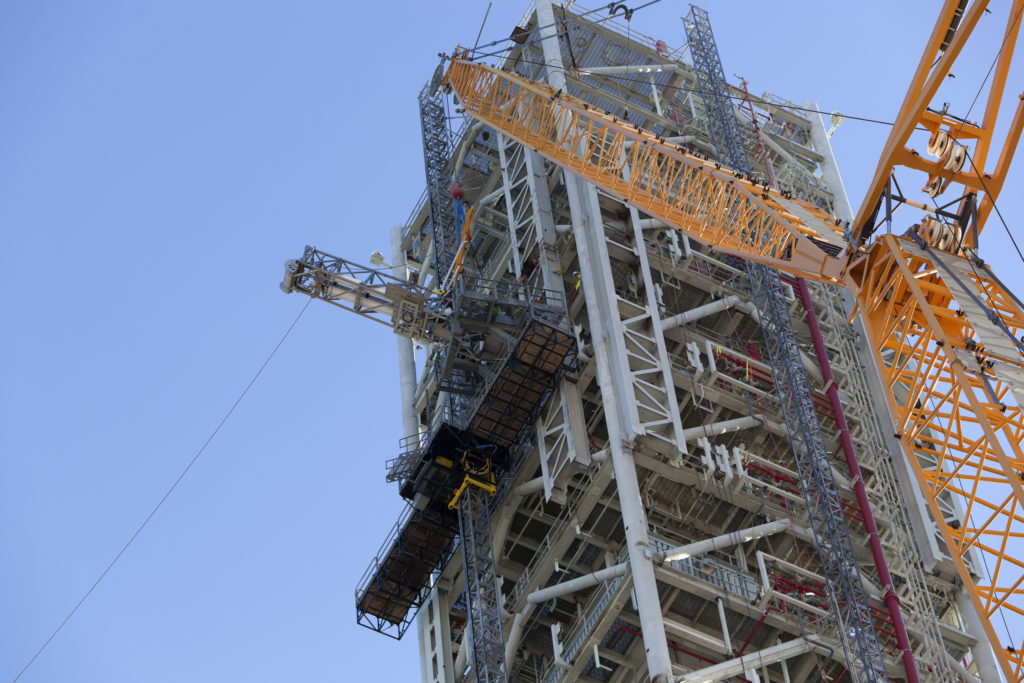
The OSMU is installed on the mobile launcher.The first launch umbilical for NASA’s Space Launch System (SLS) and Orion spacecraft was installed on the mobile launcher tower March 16 at the agency’s Kennedy Space Center in Florida. The Orion Service Module Umbilical, or OSMU, was installed high up on the tower at about the 260-foot level.

“Installation of the OSMU is a major milestone for the mobile launcher team,” said Sam Talluto, deputy project manager. “This is the first of multiple umbilicals and launch accessories that will be installed.”

The tower on the mobile launcher will be equipped with several connections, called launch umbilicals, which will connect to the SLS core stage and twin solid rocket boosters, the interim cryogenic propulsion stage and the Orion spacecraft. They will provide power, communications, coolant and fuel.

The OSMU will connect from the mobile launcher tower to the Orion service module. Prior to launch, the umbilical will transfer liquid coolant for the electronics and purge air/ GN2 for environmental control to the Orion service module that houses these critical systems to support the spacecraft. The umbilical also will provide purge air/GN2 for environmental control to the Launch Abort System. Before launch, the OSMU will tilt up and the umbilical lines will disconnect.

The first integrated launch of SLS and Orion, Exploration Mission 1, will send the spacecraft to a stable orbit beyond the moon. Orion will return to Earth and be recovered from the Pacific Ocean. The mission will demonstrate the integrated performance of the SLS rocket, Orion and ground support teams.

Photo credit: NASA/Leif Heimbold

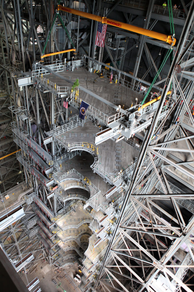
Media View New Work Platforms for NASA’s Space Launch System

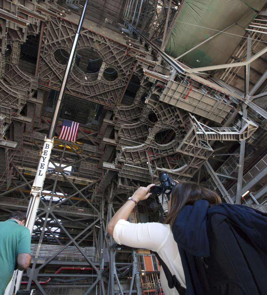
Media view new work platforms in the Vehicle Assembly Building High Bay 3.Members of the news media recently viewed the ten levels of new work platforms inside High Bay 3 of the Vehicle Assembly Building at NASA’s Kennedy Space Center in Florida. Work to install the platforms came to conclusion Jan. 12 as the final work platform, A north, was lifted, installed and secured on its rail beam on the north wall of the high bay inside the iconic facility.

Twenty platform halves will surround NASA’s Space Launch System (SLS) rocket and the Orion spacecraft atop the mobile launcher and allow access during processing for missions, including the first flight test of Orion atop the SLS.

With the goal of being a multi-user facility, the new platforms were designed to be adjusted up and down, and in and out on their rail beams in order to accommodate the SLS and its solid rocket boosters, as well as other vehicles.

Design of the new platforms began in 2010. NASA awarded a contract to modify High Bay 3 to the Hensel Phelps Construction Co. of Greeley, Colorado, in March 2014. Hundreds of NASA and contractor workers were involved in the design, manufacture and installation of the platforms.

The platform levels are A, B, C, D, E, F, G, H, J and K. With the K-level being the lowest and the A-level the highest platforms.

The mobile launcher will be rolled into High Bay 3 in the fall for multi-element verification and validation testing with the platforms.

Photo credit: NASA/Kim Shiflett

Test of Launch Umbilicals at Halfway Point for Mobile Launcher System

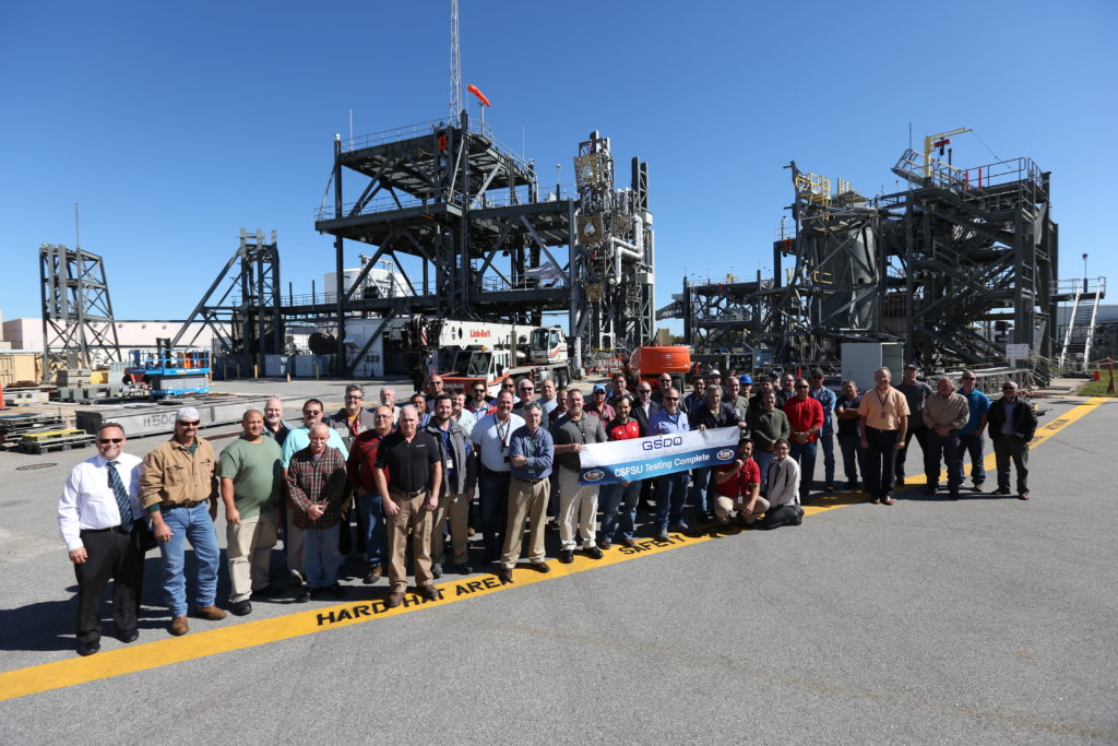
Testing is complete on the Core Stage Forward Skirt Umbilical at Kennedy Space Center.
Engineers and technicians gather at the Launch Equipment Test Facility with a banner to mark testing complete on the Core Stage Forward Skirt Umbilical. Photo credit: NASA/Cory Huston

NASA reached the halfway point on testing of the launch umbilicals for its Space Launch System (SLS) rocket and Orion spacecraft at the Launch Equipment Test Facility at the agency’s Kennedy Space Center in Florida.

The Core Stage Forward Skirt Umbilical (CSFSU) underwent testing for four months. A team of engineers and technicians with the Engineering Directorate and the Ground Systems Development and Operations Program, along with support contractors, conducted the tests. The CSFSU was attached to a Vehicle Motion Simulator at the LETF and tests confirmed the CSFSU load limits, its ability to disconnect before liftoff and that it is functioning properly and ready to be installed on the mobile launcher.

The CSFSU will be located at about the 180-foot level on the mobile launcher tower, above the vehicle liquid oxygen tank. During processing, the umbilical will be mated to the core stage forward skirt to provide commodities to the SLS rocket, and then disconnect and swing away before launch. Its main purpose is to provide conditioned air and gaseous nitrogen to the SLS Core Stage Forward Skirt.

The umbilical was transported to the mobile launcher area in December, where it is being prepared for installation on the tower of the mobile launcher.

The other umbilicals which have been tested at the LETF and are now at the mobile launcher are the Orion Service Module Umbilical, two Aft Skirt Electrical Umbilicals, two Aft Skirt Purge Umbilicals, and three of the eight Vehicle Support Posts.

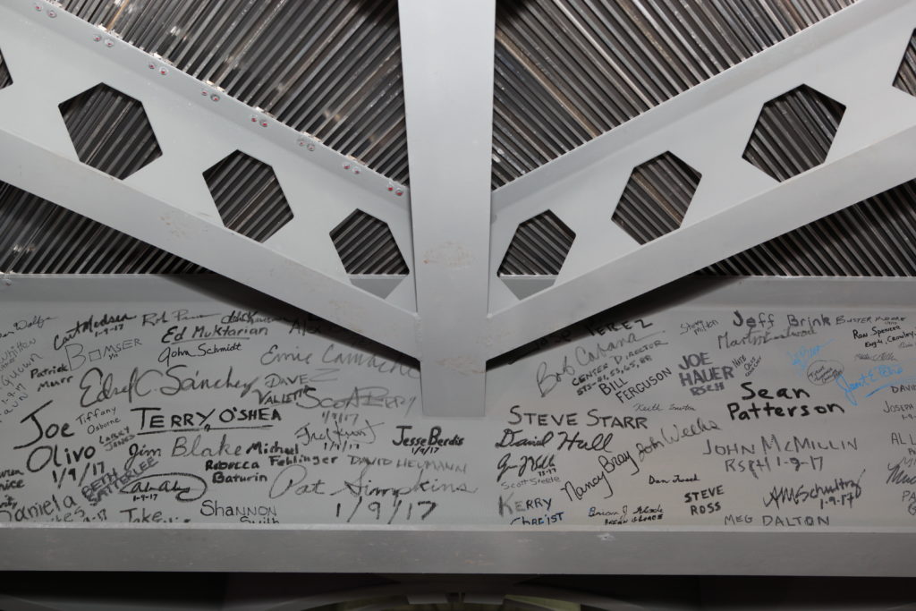
NASA, Contractor Workers Sign Final Platform in Vehicle Assembly Building

Kennedy Space Center workers sign final platform in the Vehicle Assembly Building.NASA Kennedy Space Center’s Engineering Directorate coordinated a platform beam signing event to celebrate the NASA and contractor team’s last several years of study, design, construction and installation of 20 new work platforms for NASA’s Space Launch System in the Vehicle Assembly Building (VAB).

Workers involved in the High Bay 3 platform project had the opportunity to sign one of the beams of the final work platform, A North, in the transfer aisle of the VAB.

The A platforms are the topmost and final level of 10 levels of work platforms that will surround and provide access to the agency’s Space Launch System rocket and Orion spacecraft. Orion’s first uncrewed flight atop the rocket is scheduled for late 2018.

The Ground Systems Development and Operations Program, with support from the Engineering Directorate, is overseeing upgrades and modifications to the VAB, including installation and testing of the new work platforms.

Photo credit: NASA/Dimitri Gerondidakis

Final Work Platform Lifted into Place for NASA’s Space Launch System

Platform A North InstallationThe final work platform, A north, was lifted, installed and secured on its rail beam on the north wall of High Bay 3 inside the Vehicle Assembly Building (VAB) at NASA’s Kennedy Space Center in Florida on Jan. 12.

The installation of the final topmost level completes the 10 levels of work platforms, 20 platform halves altogether, that will surround NASA’s Space Launch System rocket and the Orion spacecraft and allow access during processing for missions, including the first uncrewed flight test of Orion atop the SLS rocket in 2018.

The A platforms will provide access to the Orion spacecraft’s Launch Abort System for Orion lifting sling removal and installation of the closeout panels. The Ground Systems Development and Operations Program, with support from the center’s Engineering Directorate, is overseeing upgrades to the VAB, including the installation of the work platforms. Photo credit: NASA/Frank Michaux

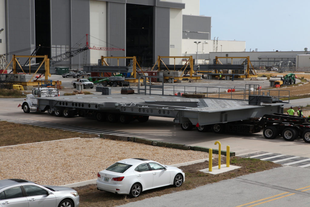
Final Work Platform Arrives for NASA’s Space Launch System

Work platform A north arrived at Kennedy Space Center in Florida on Dec. 13.The final work platform for NASA’s Space Launch System arrived Dec. 13 at the agency’s Kennedy Space Center in Florida. The second half of the A-level platforms, A north, was transported to the center by heavy-lift truck from Tillett Heavy Hauling in Titusville, Florida, and delivered to the Vehicle Assembly Building (VAB) staging area.

The platform will remain in the staging area for prep work before it is moved into the transfer aisle of the VAB. The first half of the A-level platforms, A south, arrived at the center Nov. 28. The south platform will be installed in High Bay 3 on Dec. 22. The north platform will be installed in late January 2017.

The A-level platforms are the topmost platforms for High Bay 3. The two halves will provide access to the Orion spacecraft’s Launch Abort System (LAS) for Orion Lifting Sling removal and installation of the closeout panels. Testing of the Launch Abort System Antenna also is performed on this level.

A total of 10 levels of new platforms, 20 platform halves altogether, will surround the SLS rocket and Orion spacecraft and provide access for testing and processing. NASA is preparing for the launch of Orion atop the SLS rocket from Launch Pad 39B in 2018.

Photo credit: NASA/Cory Huston