Release and Retract Test Marks Artemis I Mission Milestone

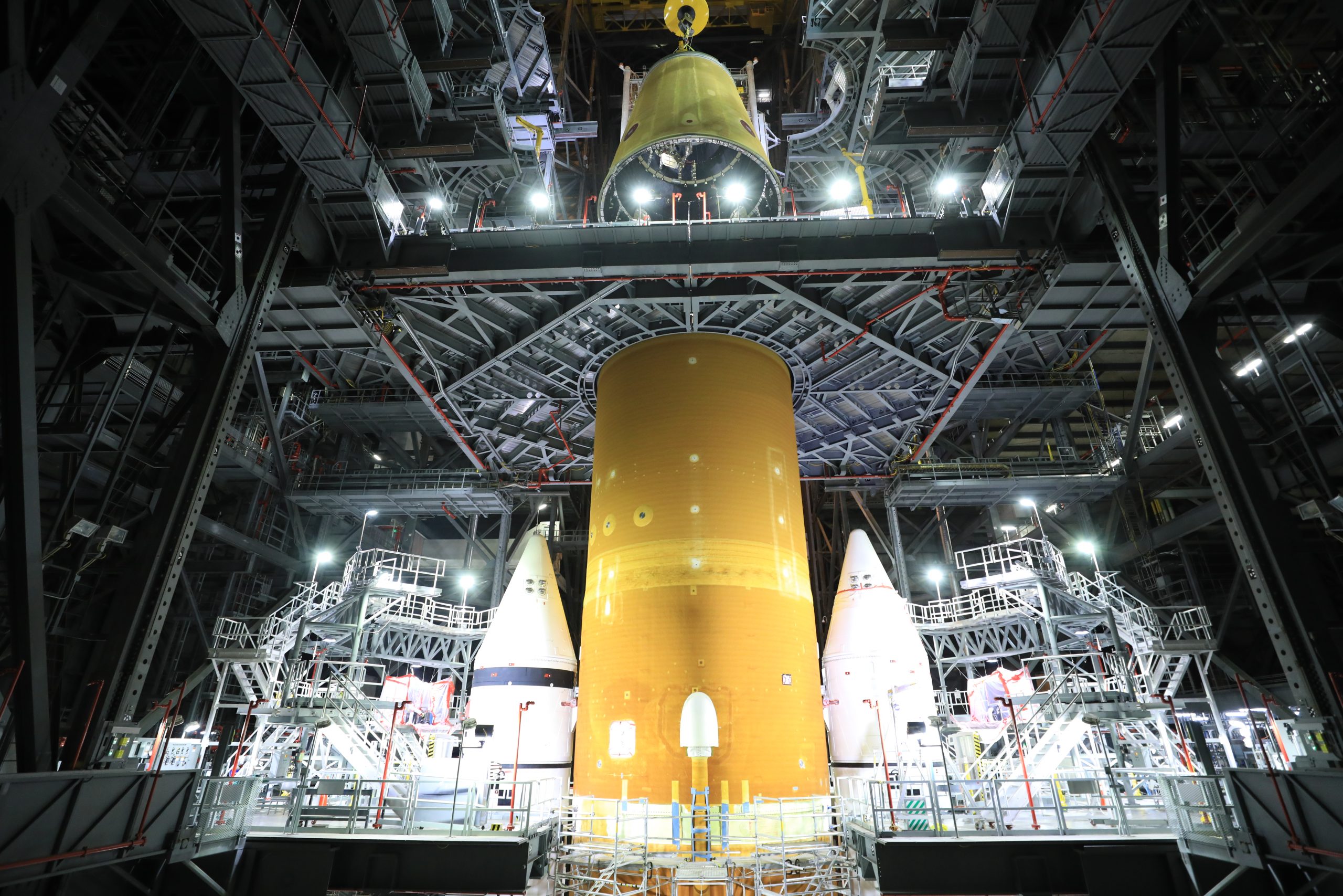
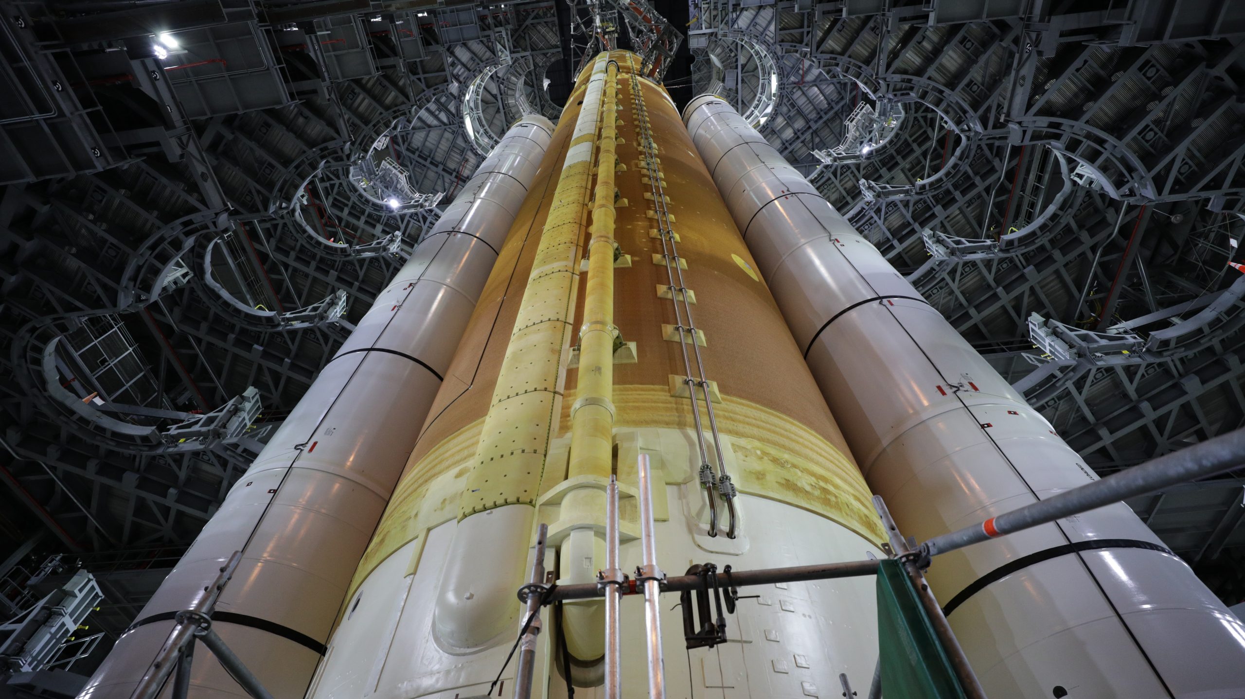
A close-up view of the Artemis I Space Launch System rocket inside High Bay 3 of the Vehicle Assembly Building at Kennedy Space Center in Florida.
A close-up view of the Artemis I Space Launch System rocket inside High Bay 3 of the Vehicle Assembly Building at NASA’s Kennedy Space Center in Florida on Sept. 20, 2021. All 10 levels of work platforms have been retracted from around the rocket as part of the umbilical release and retract test. During the test, several umbilical arms on the mobile launcher were extended to connect to the SLS rocket and then swung away from the launch vehicle, just as they will on launch day. Artemis I will be the first integrated test of the SLS and Orion spacecraft. In later missions, NASA will land the first woman and the first person of color on the surface of the Moon, paving the way for a long-term lunar presence and serving as a steppingstone on the way to Mars. Photo credit: NASA/Frank Michaux

Engineers with Exploration Ground Systems and contractor Jacobs successfully completed the Umbilical Release and Retract Test on Sept. 19 inside the Vehicle Assembly Building (VAB) at NASA’s Kennedy Space Center in preparation for the Artemis I mission.

The umbilicals will provide power, communications, coolant, and fuel to the rocket and the Orion spacecraft while at the launch pad until they disconnect and retract at ignition and liftoff.

“Previous testing at the Launch Equipment Test Facility and in the VAB refined our designs and processes and validated the subsystems individually, and for Artemis I, we wanted to prove our new systems would work together to support launch,” said Jerry Daun, Jacobs Arms and Umbilical Systems Operations Manager.

During the test, several umbilical arms extended to connect the Space Launch System (SLS) rocket and the mobile launcher. They swung away from the rocket, just as they will on launch day.

“This test is important because the next time these ground umbilical systems are used will be the day of the Artemis I launch,” said Scott Cieslak, umbilical operations and testing technical lead.

Teams will continue conducting tests inside the VAB before transporting the Orion spacecraft to the assembly building and stacking it atop the SLS, completing assembly of the rocket for the Artemis I mission.

“It was a great team effort to build, and now test, these critical systems,” said Peter Chitko, arms and umbilicals integration manager. “This test marked an important milestone because each umbilical must release from its connection point at T-0 to ensure the rocket and spacecraft can lift off safely.”

Artemis I will be the first integrated test of the SLS and Orion spacecraft. In later Artemis missions, NASA will land the first woman and the first person of color on the surface of the Moon, paving the way for a long-term lunar presence and serving as a steppingstone on the way to Mars.

Orion Spacecraft Goes ‘Shields Up’ for Artemis I

The four ogive fairings for the Orion Artemis I mission are installed on the launch abort system assembly inside the Launch Abort System Facility at NASA's Kennedy Space Center in Florida on Aug. 20, 2021.
The four ogive fairings for the Orion Artemis I mission are installed on the launch abort system assembly inside the Launch Abort System Facility at NASA’s Kennedy Space Center in Florida on Aug. 20, 2021. Photo credit: NASA/Kim Shiflett

Teams at NASA’s Kennedy Space Center in Florida are putting the final touches on the Orion spacecraft for the Artemis I mission by connecting the ogive fairings for the launch abort system (LAS) assembly.  Pronounced oh-jive, the ogive fairings consist of four protective panels, and their installation will complete the LAS assembly.

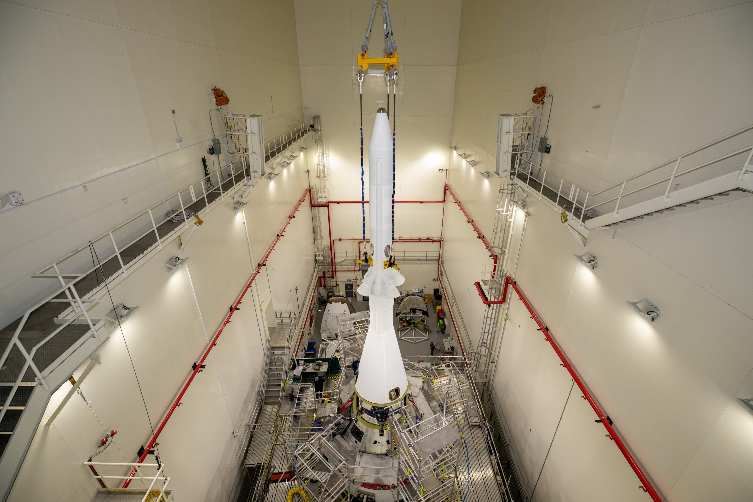
Technicians and engineers from the center’s Exploration Ground Systems and contractor Jacobs recently finished attaching the launch abort tower to the top of the Orion crew module. They then began lifting and mating the lightweight fairings, which will shield the crew module from the severe vibrations and sounds it will experience during launch. One of the fairing panels has a hatch to allow access to the crew module before launch.

During Artemis missions, the 44-foot-tall LAS will detach from the spacecraft when it is no longer needed, shortly after launching on the Space Launch System (SLS) rocket, to lighten the journey to the Moon. Although the abort motors will not be active on the uncrewed Artemis I flight test, the system is intended to protect astronauts on future missions if a problem arises during launch or ascent by pulling the spacecraft away from a failing rocket.

Once LAS installation is complete, the spacecraft will leave the Launch Abort System Facility and continue on its path to the pad, making its way to the spaceport’s Vehicle Assembly Building to be integrated with the SLS rocket ahead of the launch.

Orion Points at the Moon with Launch Abort Tower

Teams with NASA’s Exploration Ground Systems (EGS) and contractor Jacobs integrated the launch abort system (LAS) with the Orion spacecraft inside the Launch Abort System Facility at NASA’s Kennedy Space Center in Florida on July 23, 2021.
Teams with NASA’s Exploration Ground Systems (EGS) and contractor Jacobs integrated the launch abort system (LAS) with the Orion spacecraft inside the Launch Abort System Facility at NASA’s Kennedy Space Center in Florida on July 23, 2021. Photo credit: NASA/Kim Shiflett

Ahead of the Artemis I lunar-bound mission, teams at NASA’s Kennedy Space Center joined the launch abort tower to the Orion spacecraft on July 23. Working inside the spaceport’s Launch Abort System Facility, engineers and technicians with Exploration Ground Systems and primary contractor, Jacobs, lifted the system above the spacecraft and coupled it with the crew module.

The launch abort system is designed to protect astronauts if a problem arises during launch by pulling the spacecraft away from a failing rocket. Although there will be no crew Artemis I, the launch abort system will collect flight data during the ascent to space and then jettison from the spacecraft.

Next, teams will install four ogives – the protective panels that shield the upper portion of the spacecraft during its entry into orbit. Once final checkouts are complete, Orion will be integrated with the Space Launch System rocket.

Teams Add Launch Abort System to Ready Orion for Artemis I

NASA's Orion spacecraft
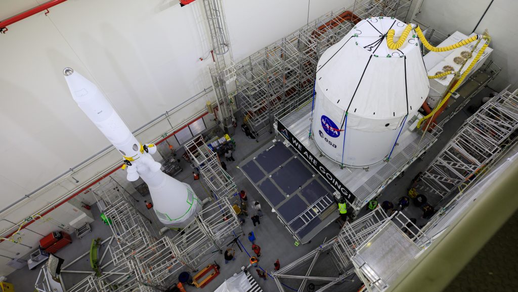
The Orion spacecraft for the Artemis I mission arrives at Kennedy Space Center’s Launch Abort System facility on July 10, 2021, after being transported from the Florida spaceport’s Multi-Payload Processing Facility earlier in the day. Photo credit: NASA/Cory Huston

The Orion spacecraft for the Artemis I mission recently completed fueling and servicing checks while inside the Multi-Payload Processing Facility at NASA’s Kennedy Space Center in Florida. The capsule has now made it to its next stop on the path to the pad – the spaceport’s Launch Abort System Facility.

Crowning the spacecraft with its aerodynamic shape, the launch abort system is designed to pull crew away to safety from the Space Launch System (SLS) rocket in the event of an emergency during launch. This capability was successfully tested during the Orion Pad Abort and Ascent Abort-2 tests and approved for use during crewed missions.

Teams with Exploration Ground Systems and contractor Jacobs will work to add parts of the launch abort system onto the spacecraft. Technicians will install four panels that make up the fairing assembly and protect the spacecraft from heat, air, and acoustic environments during launch and ascent. A launch tower will top the fairing assembly to house the pyrotechnics and a jettison motor. The system will also be outfitted with instruments to record key flight data for later study.

With successful demonstration of the system during previous tests, the abort motor that pulls the spacecraft away from the rocket and attitude control motor that steers the spacecraft for a splashdown during an abort will not be functional for the uncrewed Artemis I mission. The jettison motor will be equipped to separate the system from Orion in flight once it is no longer needed, making Orion thousands of pounds lighter for the journey to the Moon.

Once the system’s integration is complete, teams will transport the spacecraft to the center’s Vehicle Assembly Building. There, it will join the already stacked flight hardware and be raised into position atop the SLS rocket, marking the final assembly milestone for the  Artemis rocket.

Launching in 2021, Artemis I will be a test of the Orion spacecraft and SLS rocket as an integrated system ahead of crewed flights to the Moon. Under Artemis, NASA aims to land the first woman and first person of color on the Moon and establish long-term lunar exploration.

View additional photos here.

Artemis I Rocket Grows Closer to Launch

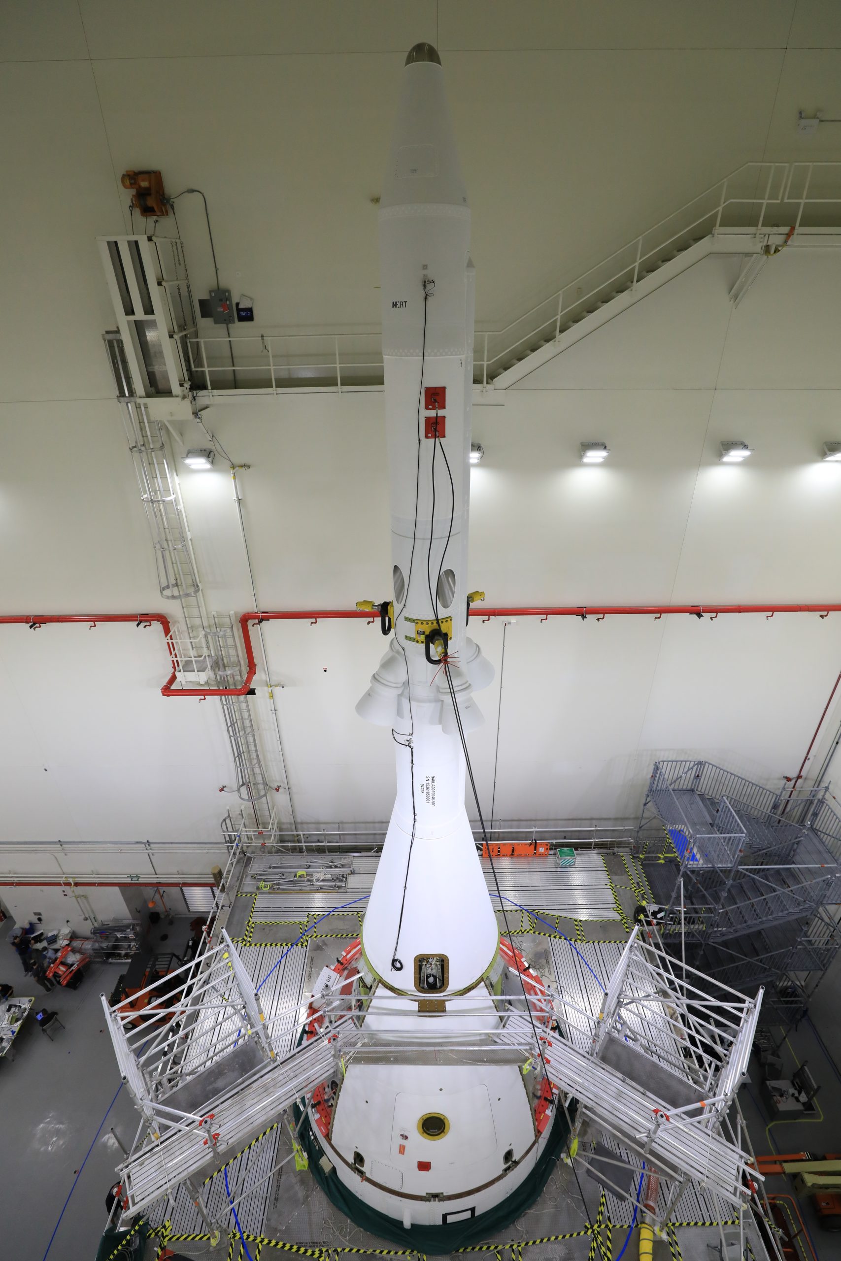
Teams with NASA’s Exploration Ground Systems and contractor Jacobs integrate the interim cryogenic propulsion stage (ICPS) for NASA’s Space Launch System (SLS) rocket with the launch vehicle stage adapter (LVSA) atop the massive SLS core stage in the agency’s Vehicle Assembly Building (VAB) at NASA’s Kennedy Space Center in Florida on July 5, 2021.
Teams with NASA’s Exploration Ground Systems and contractor Jacobs integrate the interim cryogenic propulsion stage (ICPS) for NASA’s Space Launch System (SLS) rocket with the launch vehicle stage adapter (LVSA) atop the massive SLS core stage in the agency’s Vehicle Assembly Building (VAB) at NASA’s Kennedy Space Center in Florida on July 5, 2021. Photo credit: NASA/Kim Shiflett
Teams with NASA’s Exploration Ground Systems and contractor Jacobs integrate the interim cryogenic propulsion stage (ICPS) for NASA’s Space Launch System (SLS) rocket with the launch vehicle stage adapter (LVSA) atop the massive SLS core stage in the agency’s Vehicle Assembly Building (VAB) at NASA’s Kennedy Space Center in Florida on July 5, 2021.
The ICPS is a liquid oxygen and liquid hydrogen-based system that will fire its RL 10 engine to give the Orion spacecraft the big in-space push needed to fly tens of thousands of miles beyond the Moon. Photo credit: NASA/Kim Shiflett

Leerlo en español aquí.

The Artemis I mission reached another milestone this week inside the Vehicle Assembly Building (VAB) at NASA’s Kennedy Space Center. On July 5, teams with Exploration Ground Systems and contractor Jacobs stacked the interim cryogenic propulsion stage (ICPS) atop the Space Launch System (SLS) rocket.

The ICPS’s RL 10 engine is housed inside the launch vehicle stage adapter, which will protect the engine during launch. The adapter connects the rocket’s core stage with the ICPS, which was built by Boeing and United Launch Alliance.

The ICPS will fire its RL 10 engine to send the  Orion spacecraft toward the Moon. Its European-built service module will provide the power to take the spacecraft on a journey tens of thousands of miles beyond the Moon.

Before attaching the Orion spacecraft to the rocket, teams will conduct a series of tests to assure all the rocket components are properly communicating with each other, the ground systems equipment, and the Launch Control Center.

The ICPS moved to the VAB on June 19, after technicians in the center’s Multi-Payload Processing Facility completed servicing the flight hardware inside.

Launching in 2021, Artemis I will be an uncrewed flight test of the Orion spacecraft and SLS rocket as an integrated system ahead of missions with astronauts. Under Artemis, NASA aims to land the first woman and first person of color on the Moon and establish a long-lasting presence on and around the Moon while preparing for human missions to Mars.

View additional photos here.

Next Element for NASA’s Moon Rocket Gets Stacked for Artemis I

The launch vehicle stage adapter for the Space Launch System rocket is integrated with the core stage inside the Vehicle Assembly Building.
Teams with NASA’s Exploration Ground Systems and contractor Jacobs integrate the launch vehicle stage adapter (LVSA) for NASA’s Space Launch System (SLS) rocket with the massive SLS core stage on the mobile launcher in the agency’s Vehicle Assembly Building (VAB) at NASA’s Kennedy Space Center in Florida on June 22, 2021. Photo credit: NASA/Frank Michaux

Leerlo en español aquí.

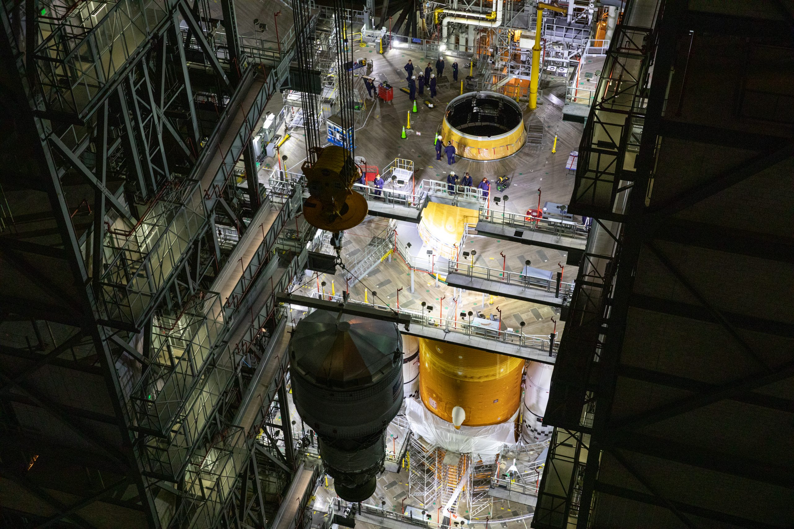
Workers at NASA’s Kennedy Space Center in Florida have stacked the launch vehicle stage adapter atop the Space Launch System rocket’s core stage inside the Vehicle Assembly Building (VAB). Engineers with Exploration Ground Systems used one of five VAB cranes to lift the adapter almost 250-feet in the air and then slowly lower it on to the core stage.

The adapter is the cone shaped piece that connects the rocket’s core stage and interim cryogenic propulsion stage (ICPS), which will provide the Orion spacecraft with the additional thrust needed to travel tens of thousands of miles beyond the Moon. Up next, the ICPS will be lifted from the VAB floor onto the stage adapter.

Launching in 2021, Artemis I will be an uncrewed flight test of the Orion spacecraft and SLS rocket as an integrated system ahead missions with astronauts. Through the series of Artemis missions, NASA aims to land the first woman and first person of color on the Moon and establish a long-lasting presence on and around the Moon while preparing for human missions to Mars.

Orion Spacecraft Adorned with Iconic NASA Worm Logo

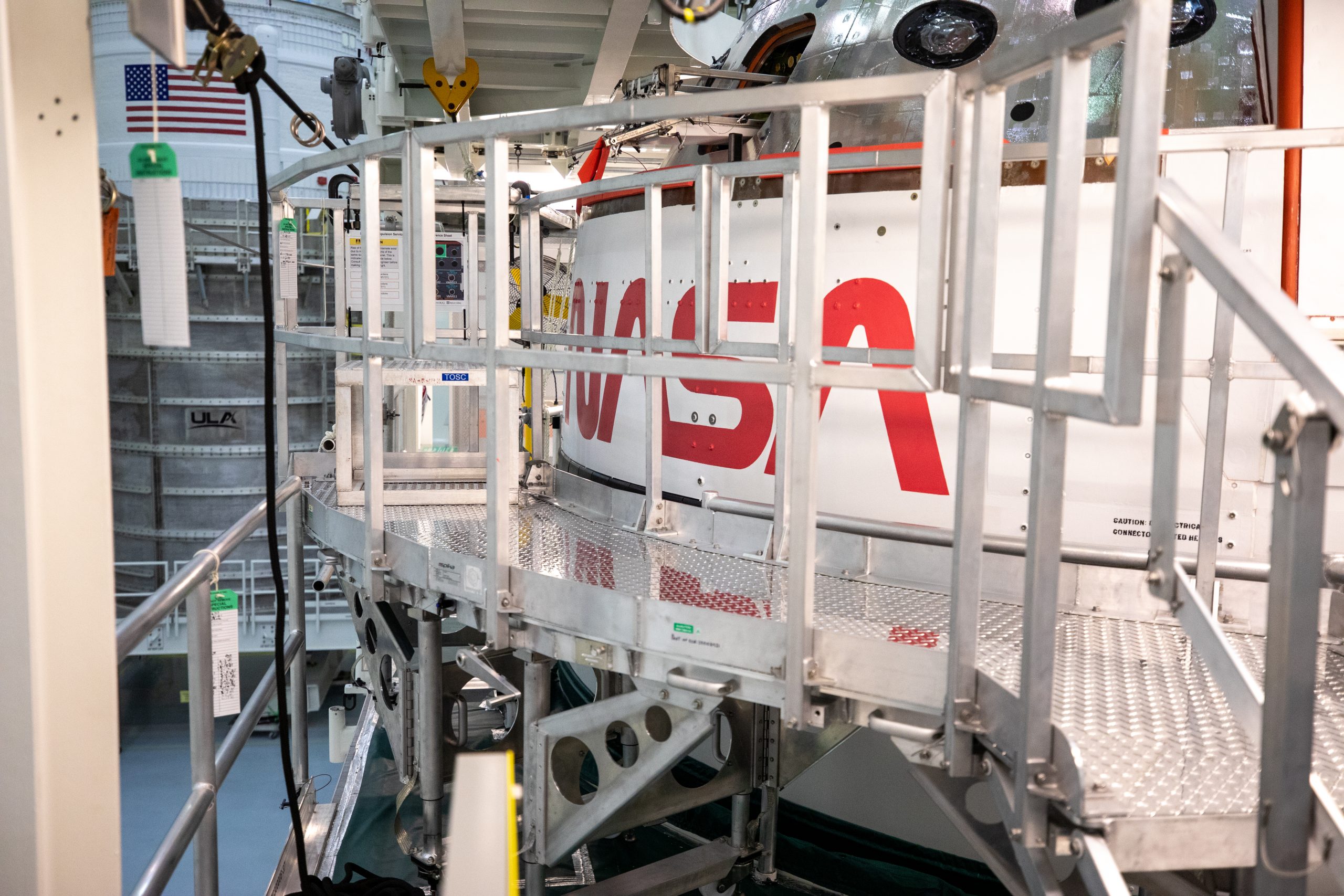
The historic worm logo is visible on the Orion spacecraft's crew module adapter inside the Multi-Payload Processing Facility.
NASA’s iconic worm logo has been added to the outward-facing wall of Orion’s crew module adapter (CMA) inside the Multi-Payload Processing Facility (MPPF) at NASA’s Kennedy Space Center in Florida. In the background is the Space Launch System rocket’s Interim Cryogenic Propulsion Stage, undergoing fueling and servicing inside the MPPF alongside the CMA. Photo credit: NASA/Glenn Benson

The Orion spacecraft receives another iconic NASA “worm” logo ahead of the Artemis I mission. On April 28 teams with the agency’s Exploration Ground Systems and lead contractor Jacobs completed painting the retro insignia on the outboard wall of the spacecraft’s crew module adapter (CMA) – the piece of hardware connecting the crew module to the European-built service module – inside the Multi-Payload Processing Facility (MPPF) at NASA’s Kennedy Space Center in Florida.

While a decal of the historic logo was added to the underside of the CMA in September 2020, having it painted on the siding of the spacecraft will make it visible as the spacecraft is poised atop the Space Launch System (SLS) rocket, awaiting liftoff from Kennedy’s Launch Pad 39B.

The worm logo was officially introduced in 1975, retired in 1992, and then made a comeback in 2020, just as NASA entered a new era of human spaceflight. In addition to its appearance on the CMA, the bright red logo also was painted on the SLS twin solid rocket boosters in August 2020.

The Orion spacecraft and Interim Cryogenic Propulsion Stage (ICPS) – the upper stage of the rocket responsible for sending Orion on its journey around the Moon – are currently being fueled and serviced in the MPPF. Once fueling is complete, Orion will move to the Launch Abort System Facility for integration of its launch abort system, while the ICPS will move to the Vehicle Assembly Building to be stacked on the mobile launcher.

Artemis I will be the first integrated test of SLS and Orion and will pave the way for landing the first woman and first person of color on the lunar surface. The mission will be a stepping stone for deep space exploration, leading the agency’s efforts under the Artemis program for a sustainable presence on the Moon and preparing for human missions to Mars.

Click here for a video of the logo being added to the CMA.

Under Pressure! New Rainbird System Will Protect Artemis II

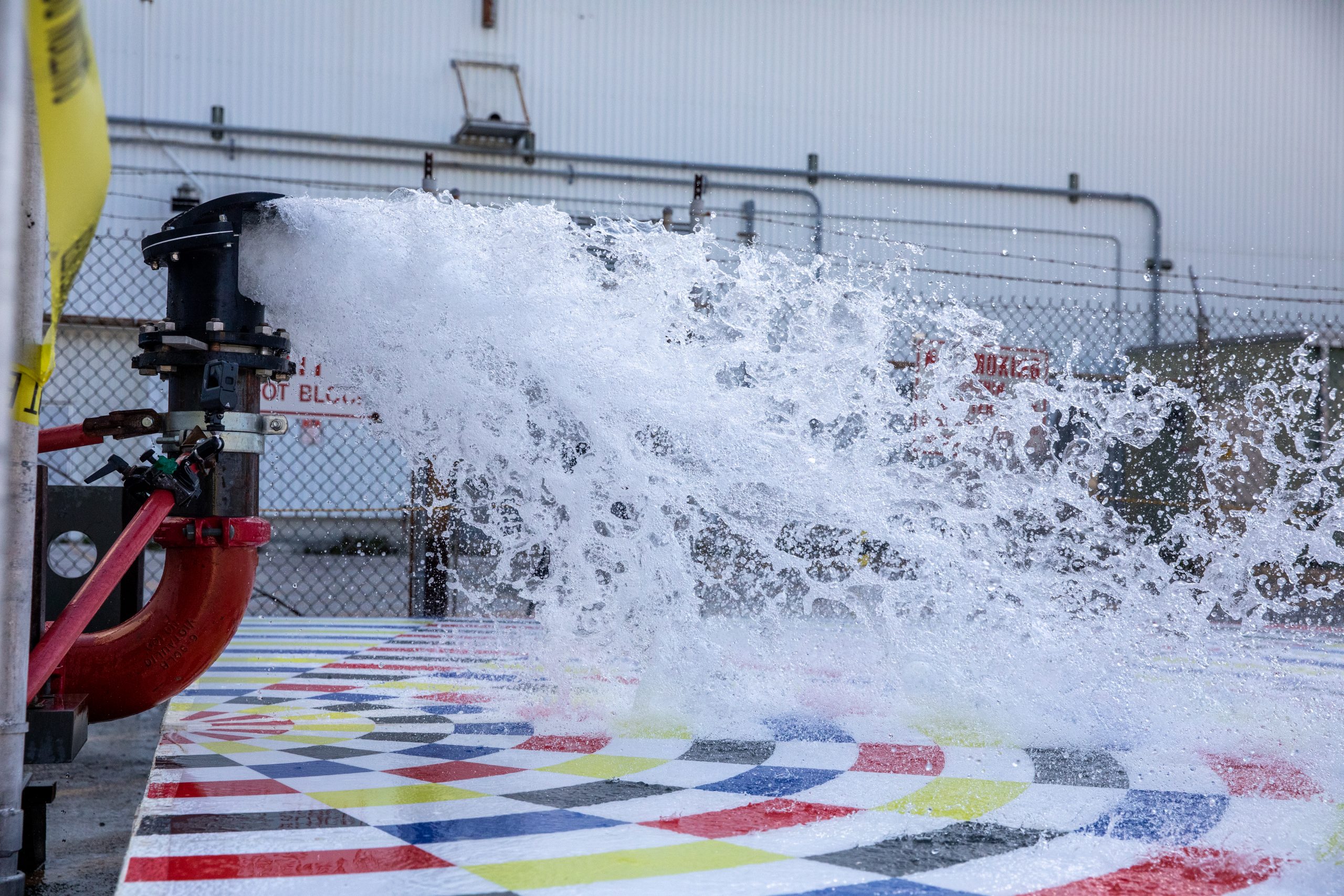
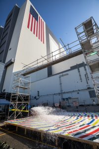
Water spraying out of a nozzle for rainbird testing for the Artemis II mission.
Water flows through a small-scale, 3D-printed nozzle during prototype testing of a new rainbird system on March 24, 2021, at NASA’s Kennedy Space Center in Florida. Photo credit: NASA/Ben Smegelsky

As NASA prepares for the uncrewed Artemis I test flight, teams at the agency’s Kennedy Space Center are also hard at work getting ready for the Artemis II mission that will send astronauts on a trip around the Moon ahead of a crewed lunar landing.

Water flows through large nozzles during rainbird testing for the Artemis II mission.
Teams with NASA’s Exploration Ground Systems and supporting contractors conduct prototype testing of a new rainbird system at the agency’s Kennedy Space Center in Florida on March 24, 2021, that can be used for the crewed Artemis II mission to the Moon. Photo credit: NASA/Ben Smegelsky

This includes assessing a new prototype “rainbird” system designed to protect the mobile launcher – as well as NASA’s Space Launch System (SLS) – when the engines roar to life. The March 24 tests included running various water pressures through small-scale, 3D-printed nozzles to capture data that can be used to develop full-scale hardware.

The rainbirds will release enough water to fill 40 swimming pools in 40 seconds. This massive volume will help absorb the heat and energy when SLS, the most powerful rocket the agency has ever built, lifts off with the Orion spacecraft from Kennedy’s Launch Pad 39B.

While upgraded rainbirds – large-scale water nozzles – have already been tested and installed on the mobile launcher for the Artemis I launch, Exploration Ground Systems (EGS) found room for improvement. This led teams from EGS and supporting contractors to start testing another prototype system to distribute water more evenly to maximize performance ahead of the Artemis II launch.

Water flows through a nozzle during rainbird testing for the Artemis II mission.
Alongside the iconic Vehicle Assembly Building at NASA’s Kennedy Space Center in Florida, teams with the agency’s Exploration Ground Systems and supporting contractors conduct prototype testing of a new rainbird system on March 24, 2021. Photo credit: NASA/Ben Smegelsky

“By running our prototype through a range of pressures, we can simulate what each of the rainbirds will see on the mobile launcher on launch day and have a better understanding of how they will perform when we scale them back up to full size,” said Dave Valletta, a design engineer at Kennedy working on the ignition overpressure protection and sound suppression (IOPSS) system.

A critical piece of the IOPSS system, the rainbird got its name decades ago when space shuttle developers noted that it looked like a garden sprayer.

“When we saw the pattern of the water discharge during the first test flow in the shuttle program, it reminded us of your common lawn sprinkler, only it did not rotate and was 100 times the size,” said Jerry Smith, a design engineer for mechanical-fluid systems at Kennedy.

Once prototype testing is complete, allowing better prediction of future spray patterns, the team will move forward with designing a preferred concept. That concept will be built and installed on the mobile launcher to undergo verification and validation testing, where the newly installed nozzles will be fully integrated with the launch pad to ensure they work as expected.

“The confidence check gained from these tests will lead us to developing full-scale nozzles for the mobile launcher,” said Gerald Patterson, IOPSS and fire suppression system operations engineer and test lead. “Once installed, they’ll provide more efficient water distribution across the deck and, ultimately, better protection to ground systems, the SLS rocket, and its crew for Artemis II and beyond.”

Artemis I Launch Team Fires Up Fueling Simulation

The Artemis I launch team rehearses loading the SLS rocket with propellants on Aug. 18, 2020.
Inside the Launch Control Center’s Firing Room 1 at NASA’s Kennedy Space Center in Florida, members of the Artemis I launch team rehearse the procedures for fueling the Space Launch System (SLS) rocket with super cold propellants, or cryogenics, on Aug. 18, 2020. Photo credit: NASA/Chad Siwik

The launch team for Artemis I is back in the firing room at NASA’s Kennedy Space Center for more practice. The team conducted a simulation on the procedures for cryogenic loading, or fueling the Space Launch System rocket with super cold propellants. During simulations potential problems are introduced to the team to test the application of firing room tools, processes, and procedures.

The Exploration Ground Systems team of launch controllers who will oversee the countdown and liftoff of the SLS rocket and Orion spacecraft will be practicing the procedures several more times ahead of launch. Special protocols have been put in place to keep personnel safe and healthy, including limiting personnel in the firing room, using acrylic dividers and adjusting assigned seating for the cryo team.

NASA Pins Down First Step in SLS Stacking for Artemis I

Inside the Rotation, Processing and Surge Facility at NASA’s Kennedy Space Center in Florida, Payton Jones, at left, a launch vehicle processing technician, and Bradley Bundy, a spaceflight technician, both with Jacobs, complete the first mate pinning of the right-hand motor segment to the right-hand aft skirt on one of the two solid rocket boosters for the agency’s Space Launch System.
Inside the Rotation, Processing and Surge Facility at NASA’s Kennedy Space Center in Florida, Payton Jones, at left, a launch vehicle processing technician, and Bradley Bundy, a spaceflight technician, both with Jacobs, complete the first mate pinning of the right-hand motor segment to the right-hand aft skirt on one of the two solid rocket boosters for the agency’s Space Launch System. Photo credit: NASA/Kim Shiflett

About a dozen technicians and engineers from Exploration Ground Systems worked together recently at NASA’s Kennedy Space Center to carry out the first step in stacking the twin solid rocket boosters that help launch NASA’s Space Launch System (SLS) rocket for the first Artemis lunar mission

Inside the Florida spaceport’s Rotation, Processing and Surge Facility, the NASA and Jacobs team completed a pin. The pinning activity involved using bolts to attach one of five segments that make up one of two solid rocket boosters for SLS to the rocket’s aft skirt. A crane crew assisted in mating the aft segments to the rocket’s two aft skirts.

Inside the Rotation, Processing and Surge Facility at NASA’s Kennedy Space Center in Florida, Pablo Martinez, a handling, mechanical and structures engineer on the Jacobs Technology Inc. Test and Operations Support Contract, prepares to insert the first of many pins that will secure the Space Launch System’s right-hand motor segment to the rocket’s right-hand aft skirt.
Inside the Rotation, Processing and Surge Facility at NASA’s Kennedy Space Center in Florida, Pablo Martinez, a handling, mechanical and structures engineer on the Jacobs Technology Inc. Test and Operations Support Contract, prepares to insert the first of many pins that will secure the Space Launch System’s right-hand motor segment to the rocket’s right-hand aft skirt. Photo credit: NASA/Kim Shiflett

A handful of the team members gained pinning experience on boosters for the space shuttle, while the rest were first-time pinners. Pablo Martinez, Jacobs TOSC handling, mechanical and structures engineer, inserted the first of 177 pins per joint to complete the first official step in stacking the SLS boosters.

The next step is a move to Kennedy’s iconic Vehicle Assembly Building to await stacking on the mobile launcher.

Manufactured by Northrop Grumman in Utah, the 177-foot-tall twin boosters provide more than 75 percent of the total SLS thrust at launch. SLS is the most powerful rocket NASA has ever built.

The SLS rocket will launch NASA’s Orion spacecraft and send it to the Moon for Artemis I — a mission to test the two as an integrated system, leading up to human missions to the Moon. Under the Artemis program, NASA will land the first woman and the next man on the Moon by 2024.

View a video of booster segment mate pinning.